PowerFlex Digital DC Drive User Manual - Publication 20P-UM001C-EN-P - July 2008
Installation and Wiring 1-39
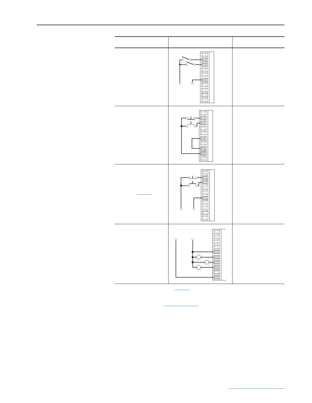
2-Wire Control
Reversing
(2)
24V DC external supply
• Set Digital Input 1:
133 [Digital In1 Sel]
= 6 “Run Forward”
• Set Digital Input 2:
134 [Digital In2 Sel]
= 7 “Run Reverse”
3-Wire Control
24V DC internal supply
• No Changes Required.
3-Wire Control
24V DC external supply
Requires 3-wire functions only
([Digital In1 Sel]). Using 2-wire
selections will cause a type 2
alarm (page page 4-7
).
• No Changes Required
Sourcing Digital Outputs
24V DC external supply
• No Changes Required
(1)
Refer to the Attention statement on page 1-32 for important bipolar wiring information.
(2)
Important: Programming inputs for 2 wire control deactivates the HIM Start and Jog buttons.
(3)
0-20mA or 4-20mA operation requires that the switch at S9, S10, or S11 be set to the “ON” position or drive
damage may occur. Refer to Table 1.L on page 1-33
.
Input/Output Connection Example
Required Parameter
Changes
Run Rev.
Run Fwd.
+24V
Neutral/
Common
11
12
13
14
15
16
17
18
19
20
11
12
1
3
14
15
16
17
18
19
20
Stop
Start
11
12
13
14
15
16
17
18
19
20
Stop
Start
+24V
Neutral/
Common
21
22
23
24
25
26
27
28
29
30
Ready
Fault
External
+24V DC
External
Neutral/
Common
Spd Thresh
 Loading...


