PowerFlex Digital DC Drive User Manual - Publication 20P-UM001C-EN-P - July 2008
Drive Start Up 2-5
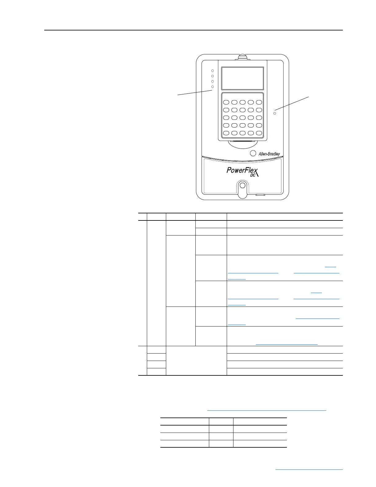
Figure 2.1 Drive Status Indicators
5. Verify the Control Voltages:
❏ Verify that the following voltages are present at I/O terminal block
1 and 2. Refer to I/O Signal and Control Wiring on page 1-35
:
# Name Color State Description
➊
STS
(Status)
Green Flashing Drive ready, but not running and no faults are present.
Steady Drive running, no faults are present.
Yellow Flashing,
Drive Stopped
A condition exists that is preventing the drive from
starting. Check parameters 1403 [Start Inhibits] and/or
1380 [Drive Alarm 1].
Flashing,
Drive Running
An intermittent type 1 alarm condition is occurring.
Check parameter 1380 [Drive Alarm 1]. Refer to Fault
Descriptions on page 4-4 and/or Alarm Descriptions on
page 4-7.
Steady,
Drive Running
A continuous type 1 alarm condition exists. Check
parameter 1380 [Drive Alarm 1]. Refer to Fault
Descriptions on page 4-4 and/or Alarm Descriptions on
page 4-7.
Red Flashing A fault has occurred. Check [Fault x Code] or view the
Fault Queue on the HIM. Refer to Fault Descriptions on
page 4-4.
Steady A non-resettable, non-configurable fault has occurred.
Check [Fault x Code] or view the Fault Queue on the
HIM. Refer to Fault Descriptions on page 4-4
.
➋
PORT Refer to the Communication
Adapter User Manual.
Status of DPI port internal communications (if present).
MOD Status of communications module (when installed).
NET A Status of network (if connected).
NET B Status of secondary network (if connected).
Terminal Number . . . Voltage to Terminal Number . . .
7 +10V 9
8 -10V 9
19 +24 - 30V 18
➋
STS
PORT
MOD
NET A
NET B
➊
 Loading...


