PowerFlex Digital DC Drive User Manual - Publication 20P-UM001C-EN-P - July 2008
3-2 Programming and Parameters
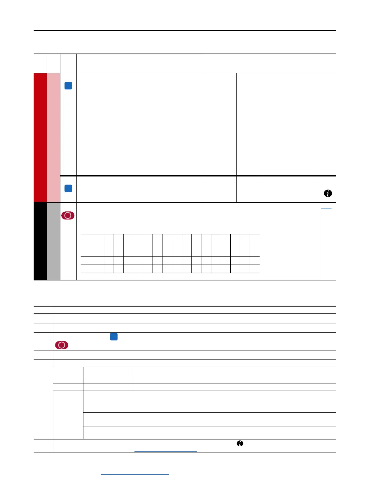
File
Group
No.
Parameter Name & Description Values
Related
SPEED COMMAND
Speed Regulator
388 [Flying Start En]
Enables/Disables the ability of the drive to connect to a
spinning motor at actual RPM when a start command is
issued.
• “Enabled” = When the drive is turned on, the speed of the
motor is measured and the ramp output is set accordingly.
The drive then runs at the set reference value.
• “Disabled” = When the drive is turned on, the ramp starts
from zero.
Main uses:
•To connect to a motor that is already spinning due to its
load (e.g. in the case of pumps, the flowing medium).
•Re–connection to a spinning motor after a fault or alarm.
Note: If the Flying Start function is disabled, ensure that the
motor is not spinning when the drive is turned on, or harsh
motor deceleration in current limit may occur.
Default:
Options:
0 =
0 =
1 =
“Disabled”
“Disabled”
“Enabled”
445 [Spd Up Gain Pct]
The Speed Up function gain as a percentage of Par 446
[Speed Up Base].
Default:
Min/Max:
Units:
0.00
0.00 / 100.00
%
COMMUNICATIONS
Masks & Owners
591 [Logic Mask]
Determines which ports can control the drive when Par 1377 [Write Mask Act], bit 15 is set to “1.” If the bit for a port is
set to “0,” the port will have no control functions except for stop. 0 = Control Masked, 1 = Control Permitted, x =
Reserved.
1377
A
A
Reserved
Reserved
Reserved
Reserved
Reserved
Reserved
Reserved
Reserved
Reserved
Reserved
DPI Port 5
DPI Port 4
DPI Port 3
DPI Port 2
DPI Port 1
Digital In
Default
xxxxxxxxxx000011
Bit
15 14 13 12 11 10 9 8 7 6 5 4 3 2 1 0
➊➌➋➏➎➍
No. Description
➊
File – Lists the major parameter file category.
➋
Group – Lists the parameter group within a file.
➌
No. – Parameter number. = The parameter is only accessible when Par 211 [Param Access Lvl] = 1 “Advanced”.
= The parameter value cannot be changed until the drive is stopped.
➍
Parameter Name & Description – Parameter name as it appears on an LCD HIM, with a brief description of the parameters function.
➎
Values – Defines the various operating characteristics of the parameter. Three types exist.
ENUM Default:
Options:
Lists the value assigned at the factory. “Read Only” = no default.
Displays the programming selections available.
Bit Bit: Lists the bit place holder and definition for each bit.
Numeric Default:
Min/Max:
Units:
Lists the value assigned at the factory. “Read Only” = no default.
The range (lowest and highest setting) possible for the parameter.
Unit of measure and resolution as shown on the LCD HIM.
Important: Some parameters will have two unit values:
• E.g.: Analog inputs can be set for current or voltage as with Par 71 [Anlg Inx Config].
Important: When sending values through DPI ports, simply remove the decimal point to arrive at the correct value (i.e. to
send “5.00 RPM”, use “500”).
➏
Related – Lists parameters (if any) that interact with the selected parameter. The symbol “ ” indicates that additional parameter
information is available in Appendix C - Application Notes on page C-1
.
A
 Loading...


