4 x Set-up and installation
ROTEX GCU compact -
19
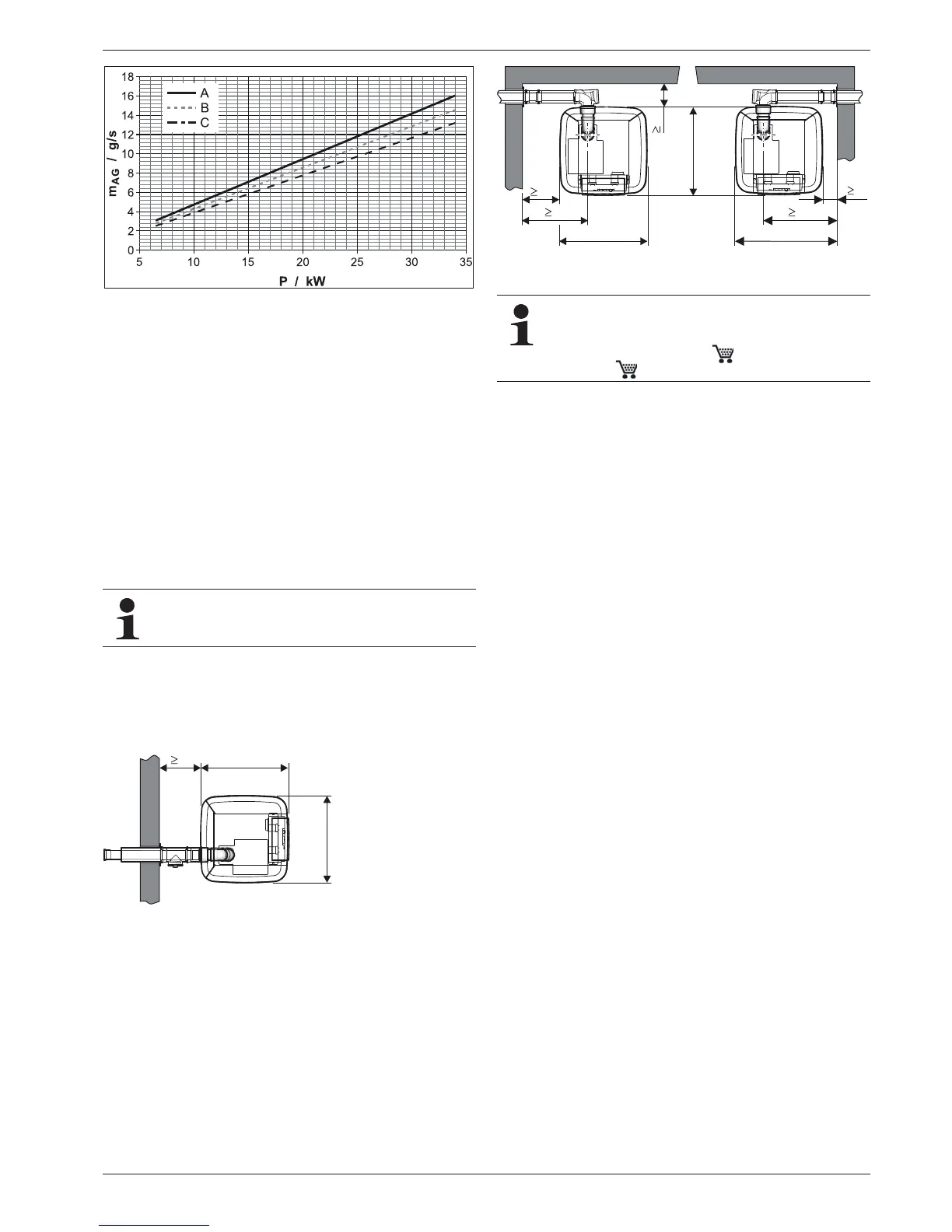
The flue gas mass flow of the plant depends on the burner output
of the ROTEX GCU compact.
4.5.2 Connecting a flue gas line
Requirements
– The flue system fulfils the requirements described in
section 4.5.1.
– The flue system fulfils any other required national or regional
safety requirements.
– The ROTEX GCU compact is installed correctly.
Connection
Ɣ Connect the ROTEX GCU compact to the flue gas system
inside the installation room (fig. 4-1 / fig. 4-2).
For dimensions, see tab. 4-1.
Ɣ Place the nameplate of the flue gas pipe in the installation
room.
a
A Natural gas E/H (G20)
B Natural gas LL/L (G25)
C Liquid gas
m
ET
Flue gas mass flow
P Burner load
Fig. 4-
12 Flue gas mass flow in dependence of the burner load ROTEX
GCU compact (all types)
We recommend to use the associated ROTEX LAS-
sets (see fig. 4-15). They satisfy all requirements and
are also fitted with special acid-proof seals.
Fig. 4-13 Plan view GCU compact Flue gas connection to the rear with
SET H (see section 4.5.3) - (for dimensions, see tab. 4-1)
Fig. 4-14 Plan view GCU compact Flue gas connection to the side with
SET
K (see section 4.5.3) - (for dimensions, see tab. 4-1)
In some cases, the resonance in the flue system can
amplify the noise at the mouth of the flue gas pipe. The
noise level can be effectively reduced with the applica-
tion of a silencer (E8 MSD, 15 45 78 bzw.
E11 MSD, 15 45 79).