38
ROTEX GCU compact -
7 x Gas burner
7 Gas burner
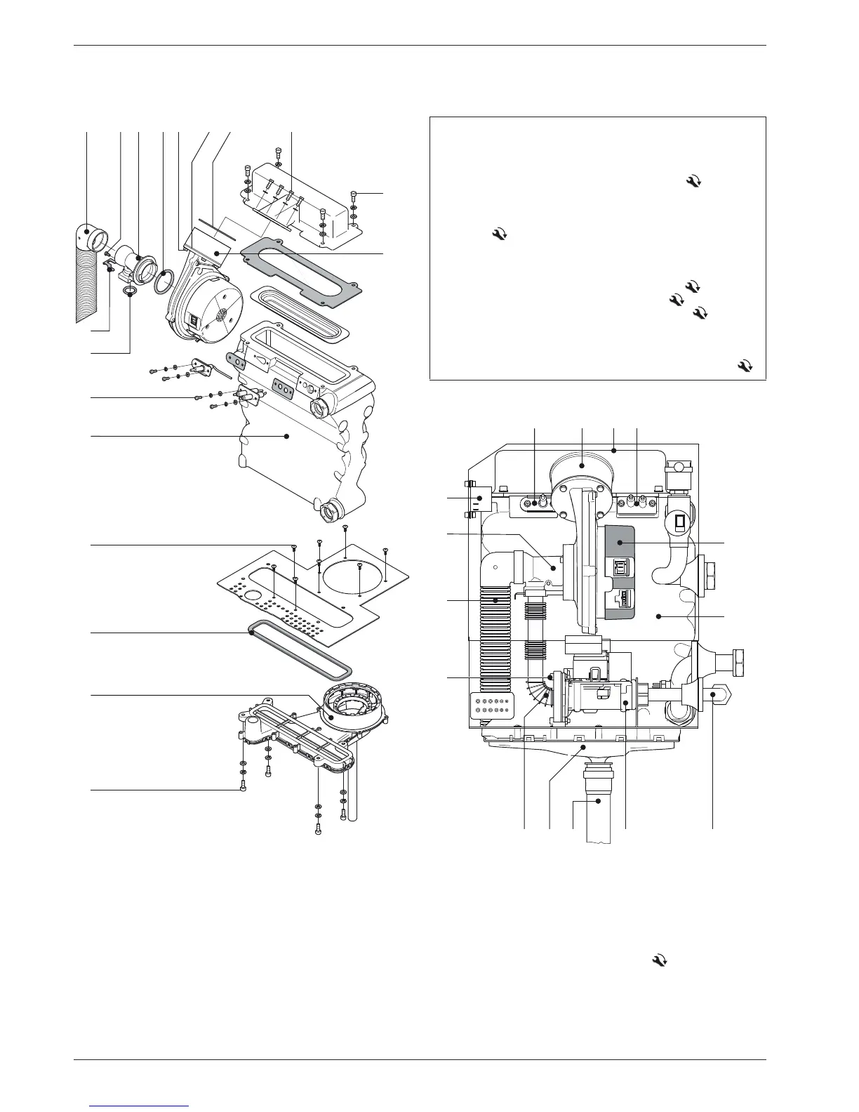
7.1 Structure and brief description
Fig. 7-1 Gas burner of the GCU compact - exploded view drawing
(for the legend, see tab. 7-1)
1 Air inlet collecting pipe
2 Safety screw (Venturi nozzle)
3 Venturi nozzle
4 O-Ring
5 4x fixing screws (flue gas collector/ boiler body)
6 flue gas collector
7 seal for flue gas collector
8 8x fixing
scre
ws (flue gas collector
/basic frame) with boiler basic
frame
9 Boiler body
10 O-Ring (Venturi nozzle-gas intake)
11 Safety clamp
12 4x fixing screws (bur
ner blower / burner flange)
13 4x fixing screws (burner flange/ boiler bo
dy)
14 4x fixing screws (burner blower / blower adapter)
15 Seal (burner blower / blower
adapter)
16 Burner flange seal
17 Burner adapter
18 4x fixing screws (ignition e
lectrodes + ionisation elect
rode)
Tab. 7-1 Legend for fig. 7-1
1 Ionisation elect
rode
2 Burner adapter
3 Burner flange
4 Ignition electrode
5 Burner blow
er
6 Boiler body
7 Gas connection G ½" female
with
connected gas h
ose
8 Safety gas control block
9 Condensate pipe
10 Flue gas co
llector
11 Gas connection line
12 Air inlet collecting
pipe
13 Venturi nozzle
14 Ignition transformer
15 2x f
ixing screws (safety-gas
con
trol block / gas conn
ection
line)
Fig. 7-2 Gas burner of the GCU compact - Side view