4 x Set-up and installation
ROTEX GCU compact -
27
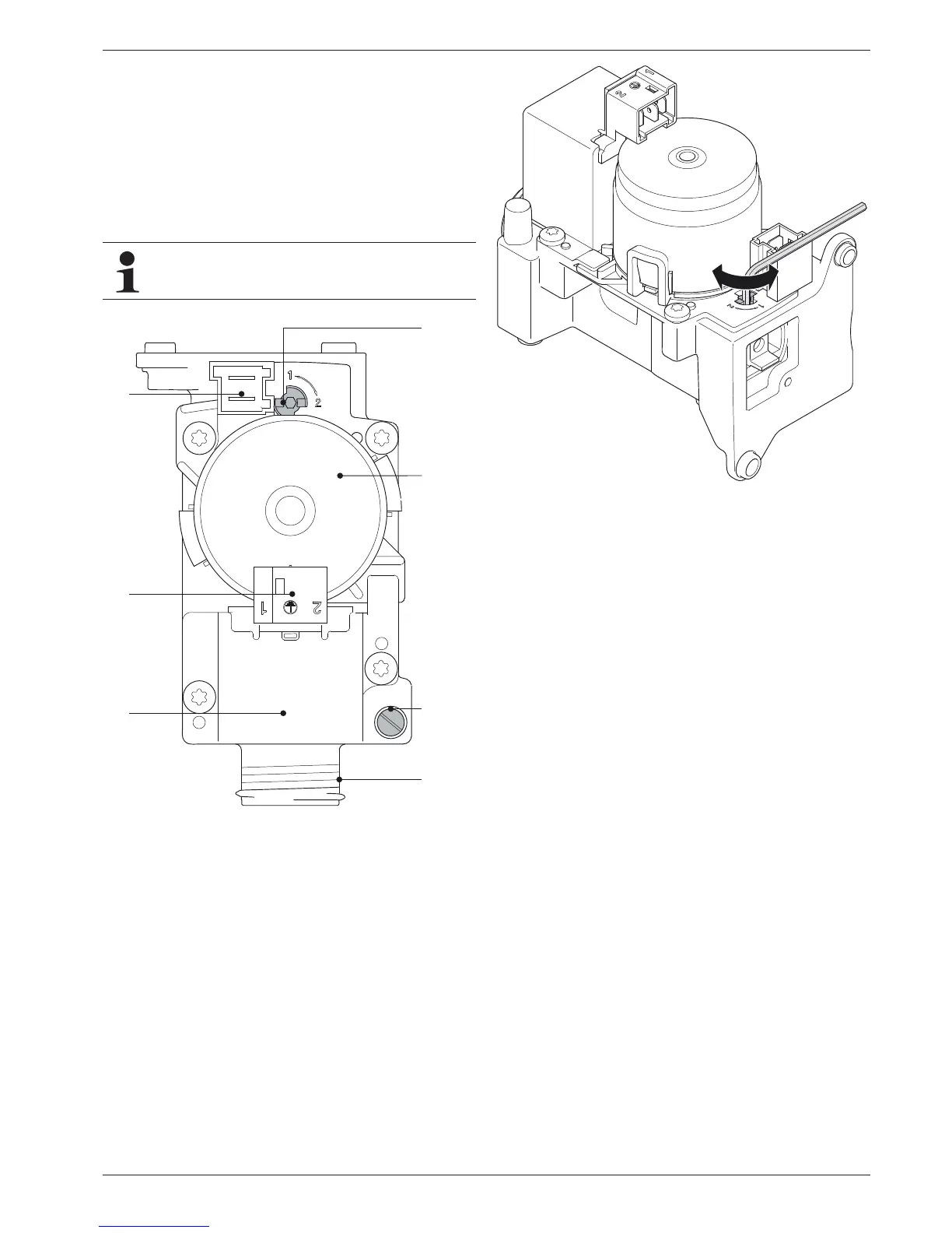
4.9.4 Checking the gas pre-installation
Ɣ Compare the available gas type with the set position of the
setting screw on the safety gas control block (fig. 4-32,
item 1).
– 1 = Natural gas
– 2 = Liquid gas
Î The gas type must match.
Î If the burner is not set to the available gas type, convert it
to the new gas type (fig. 4-33) and mark it
(see chapter 7.3 "Burner setting").
Ɣ Turn the screw in the measuring connection inlet gas
pressure (fig. 4-32, item 3.3) half a turn in an anti-clockwise
direction.
Ɣ Vent the gas line in
a professional manner.
Ɣ Insert the measuring hose of the pressure meter onto the
measuring connection inlet gas pressure (fig. 4-32, item 3.3).
Ɣ Check the inlet gas pressure.
Î If the gas inlet pressure lies below the permissible range
(tab. 12-5), inform the responsible gas supply company.
For liquid gas: Check the pressure regulator or set the
burner to the permissible gas inlet pressure
(see section 7). This adaptation must be appropriately
labelled with a suitable burner settings sticker and an
entry on the
settings type plate (fig. 3-2 / fig. 3-5, item 33).
A conversion of the gas type must also be adjusted in
the control. Observe the enclosed Control System
Instructions!
3.1 Setting screw gas type
3.2 Immersion coil
3.3 Measuring connection IN inlet gas pressure
3.4 Gas input
3.5 Gas solenoid valve
3.6 Voltage supply to gas solenoid valve
3.7 Voltage supply to immersion coil
Fig. 4-32 Check the gas inlet pressure