34
ROTEX GCU compact -
6 x Control unit
6 Control unit
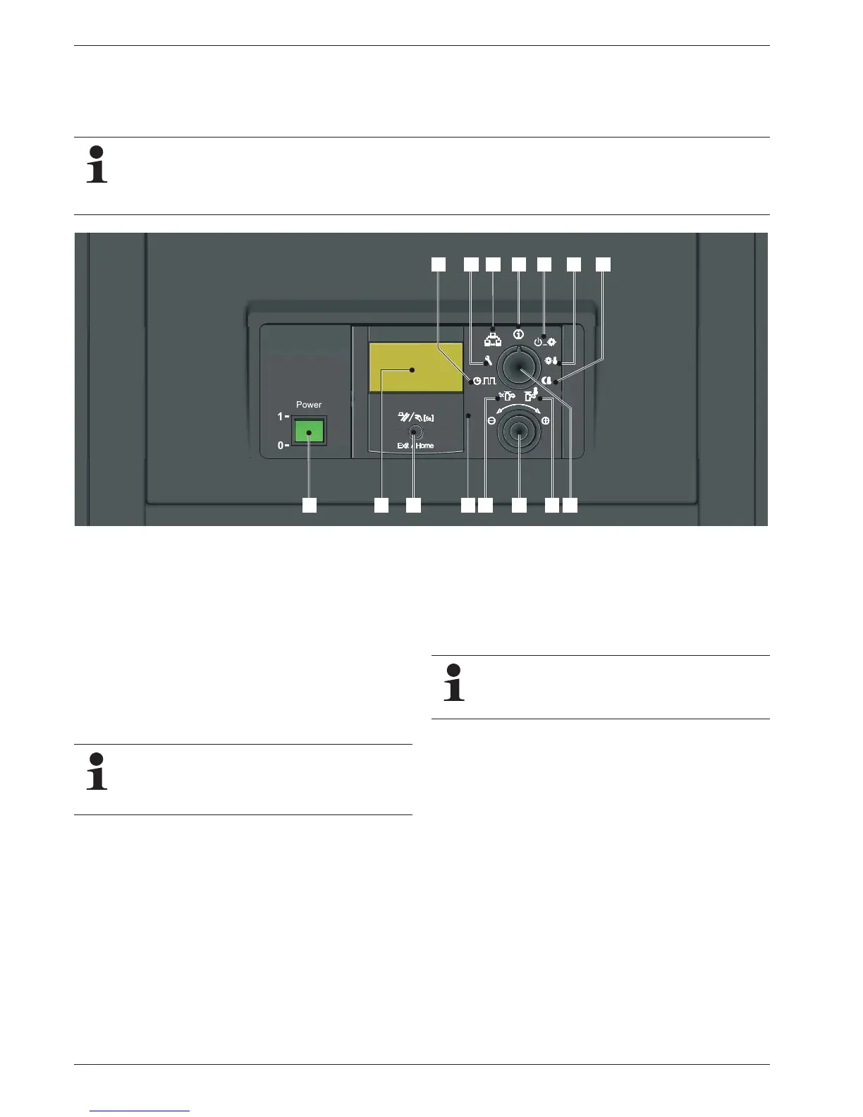
6.1 Operating elements on the boiler control
panel
Mains switch
Switch on and off the ROTEX GCU compact. When the heating
system is on, the mains switch is illuminated green.
Operating section on the RoCon B1
The operating section is equipped with a coloured backlit clear
text.
The colour of the backlighting indicates the operational status
and the programming mode:
In normal system operation, the rotary switch shou
ld be in
the po-
sition "Info".
In the display on the co
ntroller the mo
st important system temper-
atures and operational conditions are displayed.
The ROTEX GCU compact is fitted with the ROTEX RoCon BF Control. The fitted digital control system serves to a
ctuate a
direct heating circuit and a storage tank charging circuit.
It can be extended in many ways with accessory components.
A detailed description can be found in the documentation of the ROTEX RoCon BF Regl
ator.
1 Mains switch
2 Operating part RoCon B1
3 Clear text display
4 Rotary switch
5 Setting: Info
6 Setting: Ope
rating Mode
7 Setting: Set Temp Day
8 Setting: Set Temp Ni
ght
9 Setting: DHW Set T
emp
10 Setting: DHW Reheating
11 Setting: Time Pr
ogram
12 Setting: Configuration
13 Setting: System
14 Rotary button
15 Exit button (jump back, S
pecial Level, fault
rectification function)
Fig. 6-1 Operating elements on the boiler control panel
Malfunctions are generally indicated by a fault code and
a clear text fault message on the display.
For troubleshooting instructions refer to chapter 10
"Faults and malfunctions".
White: Standard lighting, normal operational display.
Red Fault status, depending on the type of fault the boiler
co
ntinues to operate w
ith restrictions.
Green: Programming mode with operator authorisation.
Blue: Programming mode with expert authorisation.
Additional information and a detailed description can be
found in the documentation "ROTEX Regulator RoCon
BF". It is included in the scope of delivery of the GCU
compact.