12 x Technical data
ROTEX GCU compact -
59
12.2 Gas type, connection pressures
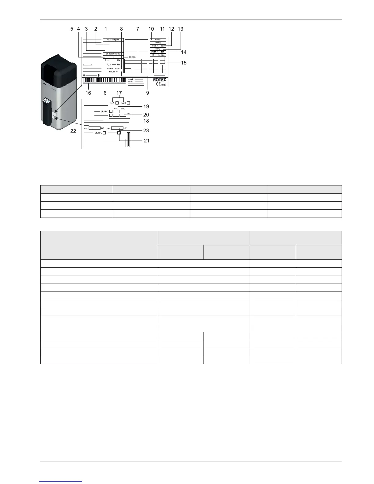
1 Type
2 Unit type
3 Product-ID (CE-Number)
4 NOx-class
5 Rated thermal load
6 Nomina
l output
7 Country of destination
8 V
oltage supply
9 Electr. power input
10 Degree of protection
11 Net weight
12 Max. permissible oper
ating pressure (heater)
13 Max. permissible oper
ating temperature
14 Max. operating pre
ssure (s
anitary)
15 D value
16 Serial number (indicate for complaints and inquir-
ies)
17 Burner configuration
18 Gas
type
19 Minimum burner load
20 Max. burner
load
21 Gas type
22 Minimum burner load
23 Max. bu
rner
load
Fig.
12-1 Information on the Type plate (top) and settings type plate (bottom)
— Information
regarding the positions see tab. 12-1 to tab. 12-6
Gas type Rated pressure in mbar Min. inlet pressure in mbar Max. inlet pressure in mbar
Natural gas E/H 20 17 25
Natural gas LL/L 20 18 25
Liquid petroleum gas 50 42.5 57.5
Tab. 12-5 Permitted gas inlet pressure
Country of destination Appliance category Nominal connection pressure in
mbar
Natural gas Liquefied
petroleum gas
Natural gas Liquefied
petroleum gas
DE II
2N3P
20/25 50
DE II
2ELL3P
20 50
AT, CH, CZ, SK II
2H3P
20 50
CH, ES, FR, GB, IE, GR, IT, HR, PT, SI, LT, SK II
2H3P
20 37
ES, FR, GR, PT, SI II
2N3P
20/25 37
NL II
2L3P
25 37
HU II
2H3P
25 30
FR II
2E+3P
20/25 37
FR II
2Er3P
20 37
DK, FI, LV, NL, NO, SE, TR I
2H
20
BE I
2E+
I
3P
20/25 37
BE I
2N
20/25
LU I
2E
20
Tab. 12-6 Countries of destination, unit categories and associated gas connection pressures (7)*
* Position numbers see fig. 12-1