15 x For the chimney sweep
15 For the chimney sweep
15.1 Data for designing the flue gas pipe
Tab. 15-1 Triple values for chimney design (flue gas flow dependent on
heat output, see fig. 4-12, page 19)
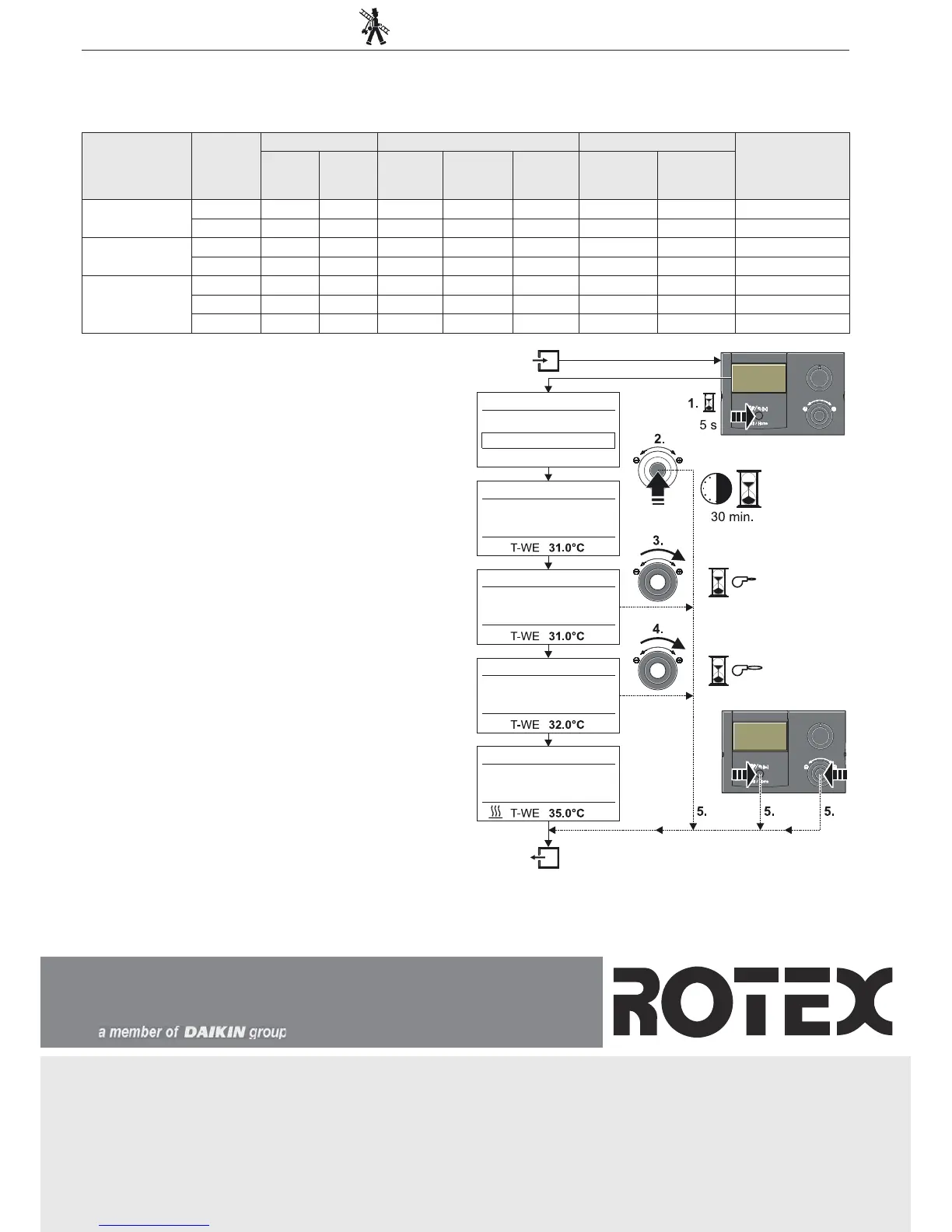
15.2 Emissions measurement
The check measurement can be made by a simply selectable automatic
function (see also "Operating Instructions - ROTEX-RoCon BF Con-
troller").
Ɣ Depress the exit button for at least 5 secs.
Î Menu "Special Level" is displayed.
Ɣ Select the programme "Emission Measurement" with the rotary
switch.
Ɣ C
onfirm the changes with a brief push of the rotary switch.
Î The following load types are available for selection:
– Off: Emission measurement is switched off, any Gas Combi Unit
compact-connected heat generator that is switched on continues
to be regulated normally.
– Base L
oad: The heat generator is switched on a
nd operated at
the minimum output of the heat generator, irrespective of the set
operating mode.
– Fu
ll Load: The heat generator is switched on and operated at the
maximum output of the
heat generator, irrespective of the set
operating mode.
Ɣ Select the load type "
Full Load" using the rotary switch,
but do not
confirm it.
Î Display: "Full Load"
Î The burner is turned on for 30 min. and is regulated at maximum
load.
Ɣ Select
the load type "Base Load" using the rotar
y switch, but do not
confirm it.
Î Display: "Base Load"
Î The modulating gas burner runs at minimum output for 30 mins.
Ɣ Cancellation and jump back by:
– Pushing the exit button or rota
ry switch again
– Selection of a different menu using
the rotary switch and confir-
mation.
Unit Burner-
load in kW
Rated output in kW Flue gas mass flow in g/s Flue gas temperature in °C Available delivery
pressure in Pa
40/30°C 80/60°C Natural
gas E/H
Natural gas
LL/ L
Liquefied
petroleum
gas
40/30°C 80/60°C
GCU compact
315/515 (BIV)
6.5 6.8 6.4 3.06 2.38 2.73 32 63 40
15.7 16.4 15.4 6.93 5.70 6.28 38 67 170
GCU comp
act
324/524 (BIV)
6.5 6.8 6.4 3,06 2.38 2.73 32 63 40
25.3 25.8 24.0 11.31 8.78 9,94 43 71 200
GCU comp
act 533
(BIV)
1) Liquid gas setting
6.5 6.8 6.4 3.06 2.38 2.73 32 63 40
30.0
1)
31.4 29.3 - - 12.59 44 73 200
32.5 33.6 31.4 15.31 12.30 - 45 74 200
Fig. 15-1 Symbolic brief instructions for emission measurement
©
ROTEX · ROTEX GCU compact · Subject to change and correction · 008.1527844_0 ·
527(;SURGXFWVGLVWULEXWHGLQ8.
'$,.,1$,5&21',7,21,1*8./WG
7KH+HLJKWV%URRNODQGV:H\EULGJH
.71<6XUUH\
)RQ
)D[
ZZZGDLNLQFRXN
527(;+HDWLQJ6\VWHPV*PE+
/DQJZLHVHQVWUDH
'*JOLQJHQ
ZZZURWH[KHDWLQJFRP