60
ROTEX GCU compact -
12 x Technical data
12.3 Tightening torque
12.4 Flow rate and residual feed height 12.5 Temperature sensor
Component Comment Tightening torque
in Nm
Fixing screws (top burner trim) fig. 4-31, item 1 3
Fixing screw (burner flange / boiler body) fig. 7-1, item 13 6
Safety screw (Venturi nozzle) fig. 7-1, item 2 3
Fixing screw (ignition electrodes / ionisation electrode) fig. 7-1, item 18 3
Fixing screw (burner blower / burner flange) fig. 7-1, item 12 6
Fixing screw (burner blower / burner adapter) fig. 7-1, item 14 4
Fixing screw (safety gas control block / gas connection line) fig. 7-2, item 15 2
Temperature sensor and sensors all Max. 10
Hydraulic line connections (Water) Thread 1" 25 - 30
Tab. 12-7 Tightening torque
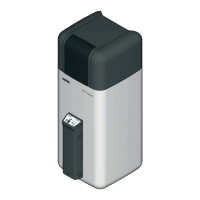
Δ
p
R
Remaining pumping height
m
H
Flow heating network
1 Modulation range
Fig. 12-2 Residual feed height GCU compact (heater side)
m
H
Flow heating network Q Heating output
Fig. 12-3 Required throughput volumes dependent on the heating out-
put and the design temperature spread
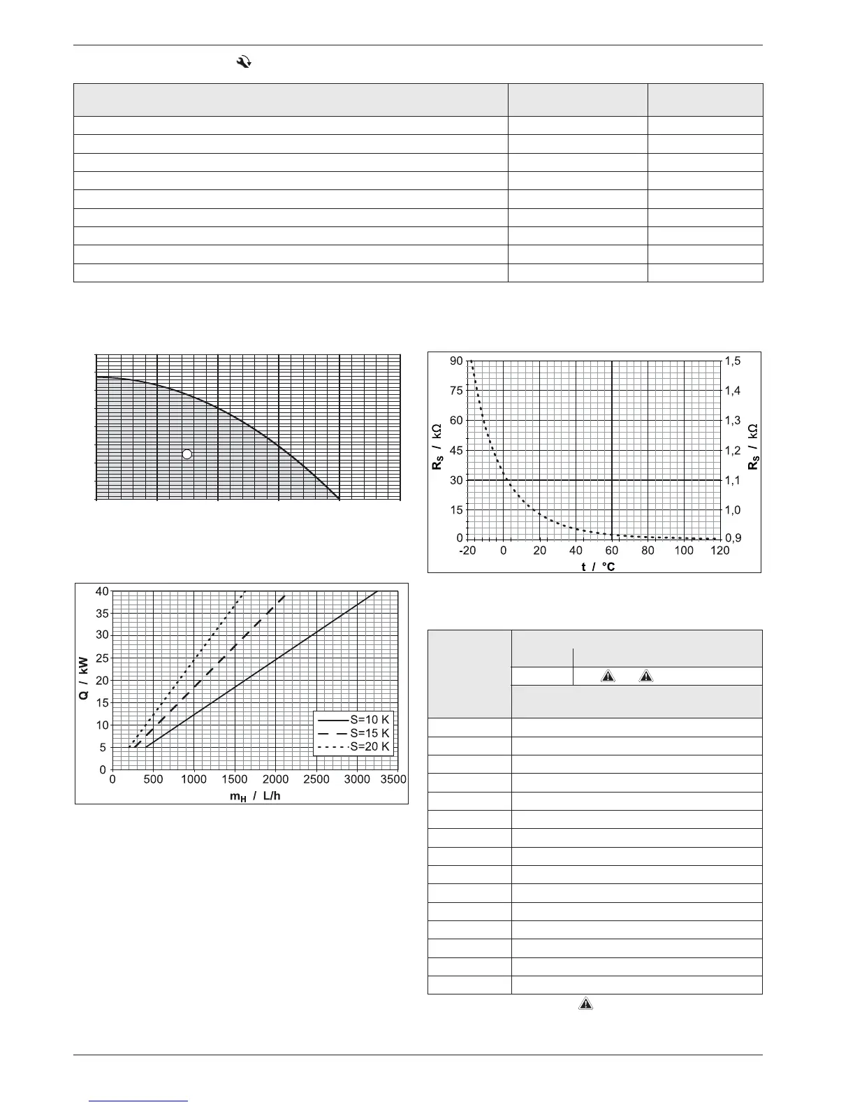
R
S
Sensor resistance T Temperature
Fig. 12-4 Resistance characteristics of the temperature sensor
Measured
temperature
in °C
Temperature sensor
Type Specification *
NTC
Sensor resistance in Ohm according to
standard or manufacturer's indications
-20 98660
-10 56250
033210
10 20240
20 12710
30 8195
40 5416
50 3663
60 2530
70 1782
80 1278
90 932
100 690
110 519
120 395
* Key see tab. 8-1 Safety devices
Tab. 12-8 Resistance values of the temperature sensor
t
V
, t
R
,W
9
t
AU
, t
DHW
, t
Mi