12 x Technical data
ROTEX GCU compact -
61
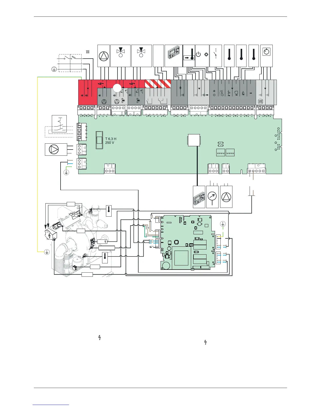
12.6 Electrical connection diagram
J1 3-pin circuit board connector with pump ca-
ble mains)
J2 4-pin circuit board connector with valve ca-
ble
J3 6
-pin circuit board connector (not occu-
pied)
J5 3-pin circuit board connector with pressure
sensor cable
J6 4-pin circuit board connector with clamped
mains cable and earthing slots
J7 2
-pin circuit board with PWM signal cable
for external heating circulation pump
J8 12-pin circuit board connector to connect
sensors and control lines
J9 5-pin circuit board connector (not occu-
pied)
J10 3-p
in circuit board connector with mains ca-
ble for automatic firing CM434
J11 5-pin circuit board connector with mains ca-
ble for automatic firing CM434
J12 4-pin circuit board connector:
GCU compact 3xx: Not assigned
GCU compact 5xx: Connection 3-way
change valve (
3UVB1)
J13 4-pin circuit board connector for connecting
additional regulating system components
(CAN-Bus)
J14 3
-pin circuit board connector for clamping a
circulation pump
J15 4-pin circuit board connector with switch
cable
J16 4
-pin circuit board connector for connecting
a room thermostat (digital demand contact)
Mains supply 230 V, 50 Hz
Fig. 12-5 Wiring diagram ROTEX GCU compact
!"#$%
#&'(!
)*(+!'&+,(
-./(,)+0
/
&
/
1
222
3242
%
!1
%
!1
%
%
"!!!!%
#
))3!
))3!
#
"/
5%
222
/
( &'6
( &'
/
#
/
#
1.77
8
8
$9
6
6
( &'
%
!-):;.-/!<<
%
!-):;.-/!<<
?