30
ROTEX GCU compact -
4 x Set-up and installation
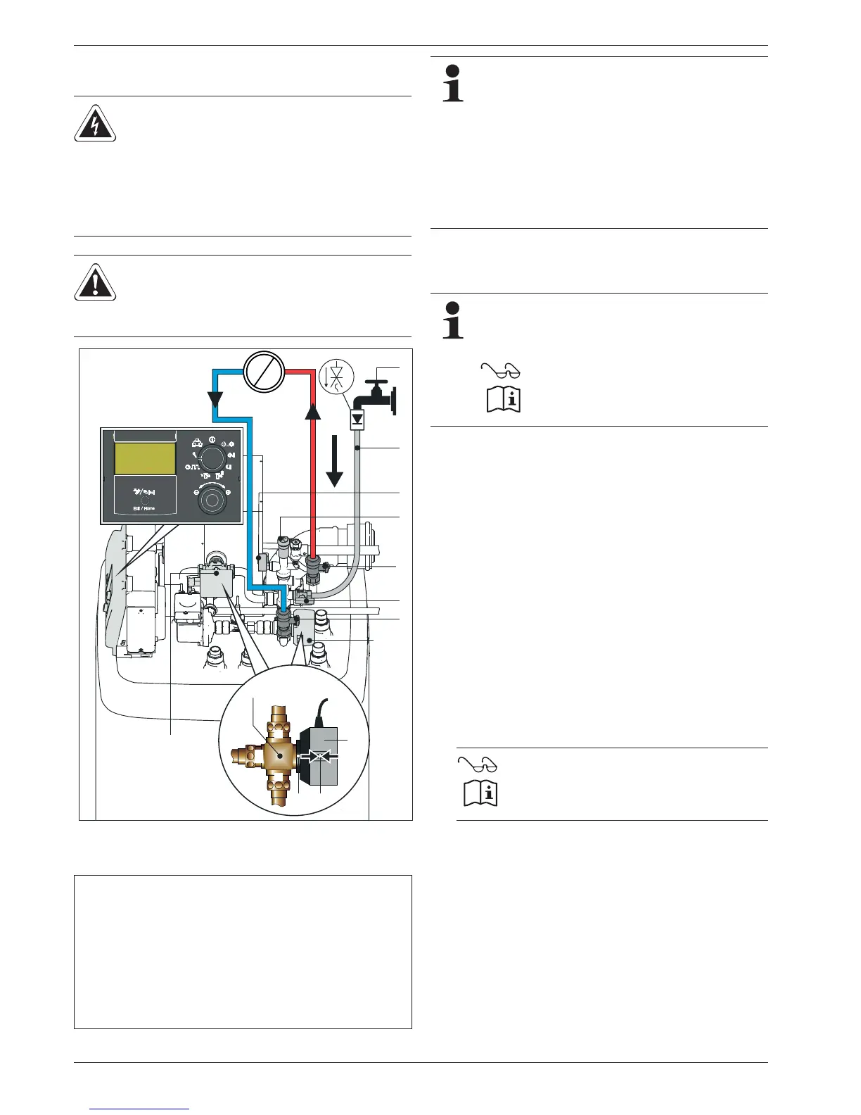
4.11.4 Filling the heating system and the storage tank
charging circuit
1. Engage the hand lever (fig. 4-35, item 5.3) of the 3-way valve
(3UVB1/3UV DHW) into the centre position (as-delivered
condition: only possible when de-energised).
2. Connect the filler hose (fig. 4-35, item 1) with flow-back
preventer (1/2") to the KFE cock (fig. 4-35, item 2) and secure
with a hose clip to prevent it from coming off.
3. Open the water cock (fig. 4-35, item 6) in the supply line.
4. Open the KFE cock (fig. 4-35, item 2) and observe the
pressure gauge (fig. 4-35, item 8).
5. Fill the system with water until the marking of the system
overpressure is roughly in the centre of the green range of the
pressure gauge display.
6. Close KFE cock (fig. 4-35, item 2).
7. Vent the entire heating network (open the system control
valves).
8. Check the water pressure on the pressure gauge again and
top up with water via the KFE cock (fig. 4-35, item 2).
9. Close the water cock (fig. 4-35, item 6) in the supply line.
10. Disconnect the filling hose (fig. 4-35, item 1) with backflush
prevention from the KFE cock (fig. 4-35, item 2).
DANGER!
During the filling procedure, water may escape from
an
y leaky areas which can cause a
n electric shock if it
comes into contact with live parts.
Ɣ Disconnect the GCU compact before filling.
Ɣ After filling for the first time and before switching
the GCU compact at the mains
switch, check that
all electrical parts and joints are dry.
WARNING!
Contamination of drinking water endangers the health.
Ɣ When filling the heating system prevent any back-
flow
of heating water into the drinking water piping.
Fig. 4-35 Fill the heating system and the storage tank charging circuit
(shown on the GCU compact 5xx)
1 Filling hose with backflush
prevention
2 KFE cock
3 Ball cock heat
ing system-
inflow
4 Ball cock heating system -
return flow
5.1 Valve dr
ive
5.2 Unlock button for the drive
locking mechanism
5.3 Ha
nd lever
6 Water co
ck
7 Automatic ble
eder
8 Pressure gauge
3UV DHW
3-way distribution valve
3UVB1
3-way mixer valve
Tab. 4-4 Legend for fig. 4-35
In the as-delivered condition, the 3-way valves
(3UVB1/3UV DHW) are in the filling position. The
hand lever (fig. 4-35, item 5.3) is in a latched
middle position. The 3-way valve partly releases
both flow paths.
If the hand lever (fig. 4-35, item 5.3) faces away from
the valve body (valve setting AB-B) or towards the
valve body (valve setting AB-A), the 3-way valve will
need to be brought into the centre position before filling
(see work step 2 and the enclosed operating instruc-
tions "ROTEX Control RoCon BF").
The centre position is only stable when the 3-way valve
is
de-energised. The 3-way-switch valve unlocks
automatically when the voltage at the drive motor for
the valve position AB-A is applied.
ZB_RoCon_VentFkt (008.1534699)
11.
ZB_RoCon_VentFkt (008.1534699)
89%
89'+:
89'+:89%