6 x Control unit
ROTEX GCU compact -
35
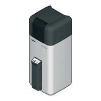
6.2 Replacing the operating section RoCon B1
Removing the operating section
Ɣ Release the lugs on both sides of the operating section by
sliding in a small flat bladed screwdriver in (fig. 6-2, item 1)
and pull the operating section out to the front.
Ɣ To remove completely,
unplug the communication cable
(fig. 6-2, item 3) on the reverse side of the operating
section.
Fitting the operating section
Ɣ Plug in the communication cable on the back of the operating
section.
Ɣ Slide the operating section into the switching panel cut-out
until the lugs cli
ck in place again.
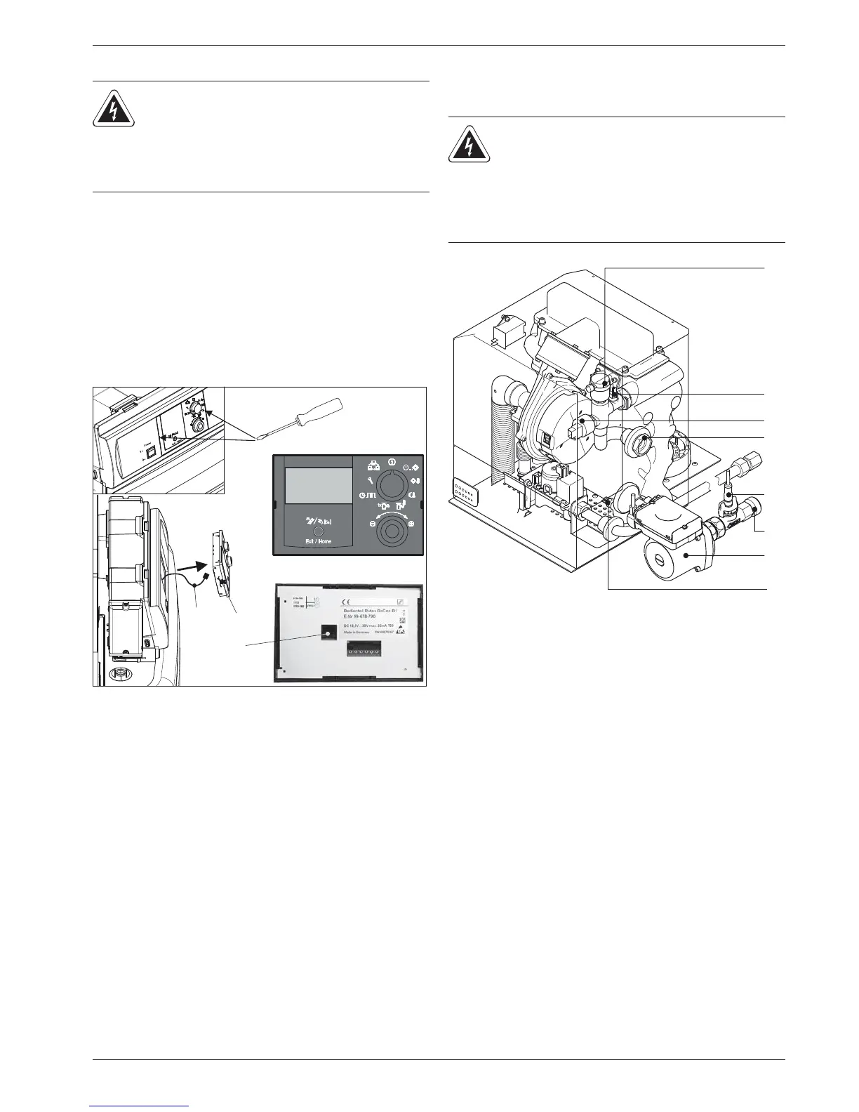
6.3 Changing the sensors
Internal sensors (fig. 6-3) can be changed without having to open
the boiler control panel.
WARNING!
Live parts can cause an electric shock on contact and
cause life-threatening burns a
nd injuries.
Ɣ Before beginning work on live parts, disconnect
them from the power supply (switch of fuse, main
switch) and secure against unintentional restart.
A Front view
B Rear view
1 Operating section RoCon B1
2 Plug connection for commu-
nication cable
3 Communication cable
Fig. 6-
2 Removing/fitting the operating section
WARNING!
Live parts can cause an electric shock on contact and
cause life-threatening burns and injuries.
Ɣ Before beginning work on the ROTEX GCU
compact disconnect it from the power supply
(switch off the fuse, main switch) and secure
against unintentional restart.
1 Automatic bleeder
2 Flow temperature sensor t
V1
3 Pressure sensor
4 Heat cell flow
5 Heat cell return flow
6 Retur
n temperature sensor t
R2
7 Heating circulation pump
8 FLS1 flow sensor with return temperatur
e sensor t
R1
Fig. 6-3 Position of the sensors at the boiler