28
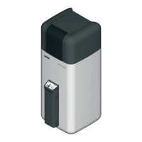
ROTEX GCU compact -
4 x Set-up and installation
4.10 Optional connections
4.10.1 Mixer module RoCon M1
The RoCon M1 mixer module can be connected to the ROTEX
GCU compact, which is controlled via the electronic boiler
control.
4.10.2 Room control RoCon U1
For remotely setting operating types and set room temperatures
from a different room, a separate room control RoCon U1 can be
connected for each heating circuit.
4.10.3 Internet Gateway RoCon G1
The Control can be connected to the Internet via the optional
Gateway RoCon G1. This means that the ROTEX GCU compact
can be controlled remotely via mobile phone (using an App).
4.11 Filling the system
Do not fill the ROTEX GCU compact until all installation activities
have been completed, in the order shown as follows.
4.11.1 Check the water quality and adjust the pressure
gauge
Ɣ Observe the instructions concerning the water connection
according to section 4.6.
Before filling up the system for the first time, you will need to set
the correct minimum pressure marking on th
e glass of the
pressure gauge (in safety group SGB GCU, 15 60 13):
Ɣ Rotate the pressure gauge glass in such a way that the
minimum pressure mark corresponds to the syste
m height
+2 m (1 m water column corresponds to 0.1 bar).
4.11.2 Filling the hot water heat exchanger
Ɣ Open the shutoff valve for the cold water supply pipe.
Ɣ Open the withdrawal tap connections for hot water to allow
you to set as large a draw-off rate as possible.
Ɣ Once water has been discharged
from the tap connections,
do not interrupt the cold water flow; this will ensure that the
heat exchanger will be fully vented and that any impurities or
residue will be discharged.
4.11.3 Filling the storage tank
Without installed solar system
Ɣ Remove the filling hose with backflush prevention (1/2") to
the connection "Solar inflow " (fig. 4-34, item 20).
Ɣ Fill the storage tank of the GCU compact until wa
ter begins
to escape from the overflow connection (fig. 4-34,
item 23).
Ɣ Disconnect the filling hose with backflush prevention (1/2")
again.
With installed solar system
Ɣ Mount the KFE cock (customer provision) to the das optional
threaded connector (1" IG, 1¼" AG) of the solar regulation
and pump unit (536).
Ɣ Connect the filling hose with backflush prevention (1/2"
) to
the KFE cock installed before.
Ɣ Fill the storage tank of the GCU compact until water begins
to escape from the overflow connection (fig. 4-34,
item 23).
Ɣ Discon
nect the filling hose with backflush prevention (1/2")
again.
A separate installation
manual is included with this
component. See the enclosed Control System Instruc-
tions for the instructions on setting and operation.
A separate installation manual is included with this
compon
ent. See the enclosed Co
ntrol System Instruc-
tions for the instructions on setting and operation.
A separate installation manual is included with this
component. See the enclosed Co
ntrol System Instruc-
tions for the instructions on setting and operation.
CAUTION!
Escape of flue gas from the system will be damaging
to health.
Ɣ Before commissioning the ROTEX GCU compact,
fill the storage tank container up to the overflow
mark.
CAUTION!
Filling the storage tank container with excessive water
pressure or with too high a
flow speed can cause
damage to the GCU compact.
Ɣ Only fill with a water pressure <6 bar and a flow
speed <
15 l/min.
UK only!
CAUTION!
If filling or topping up the storage tank is done by
means of the boiler filling and drain valve, a temporary
filling loop must be used with the appropriate backflow
prevention device in accordance with clause G24.2,
Guidance to the Water Supply (Water Fittings)
Regulations 1999.