24
ROTEX GCU compact -
4 x Set-up and installation
Control panel circuit board
Tab. 4-3 Legend for fig. 4-24
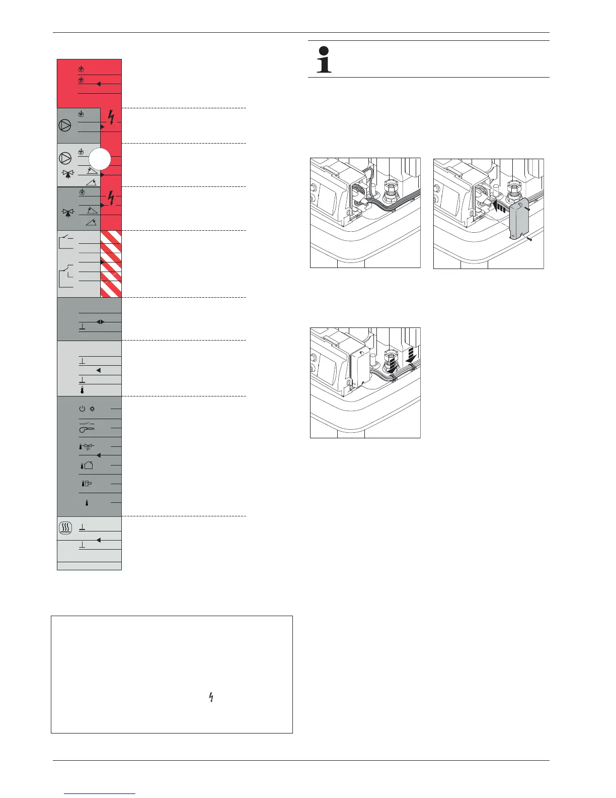
Ɣ Install the cabling leading outdoors into the strain relief
devices in the right side of the housing (fig. 4-25). The same
procedure applies on the left side of the housing for the
internal cabling in the event of an exchange.
Ɣ Re-install the side housing cover which was removed before
(fig. 4-26).
Ɣ Secure cables leading outdoors to the storage container
(fig. 4-27).
Ɣ Establish the mains connection between ROTEX GCU
compact and automatic fuse on the junction box of the
domestic power supply (see chapter 12 "Technical data",
fig. 12-5).
– Use an all-pole disconnecting main switch on the junction
box of the domestic power supply (separate isolator in
accordance with EN 60335-1).
– Ensure that the polarity is correct.
Ɣ After comple
ting all electrical connection tasks, re-establish
the power supply to the automatic fuse concerned.
Fig. 4-24 Connection diagram of the circuit board connectors and cable
colours of the factory-installed connection cables (for legend
see tab. 4-3
A detailed description of the individual connections can
be found in section 12.6.
Fig. 4-25 Install cables in
chicanes.
Fig. 4-26 Install the right housing
cover.
Fig. 4-27 Fasten cabling on the storage container.
JQJH
JQJH
EO
EU
EO
EU
VZ
EO
EU
VZ
QE
QE
EU
JU
EO
ZV
EU
EO
EU
EO
QE
QE
VZ
-
-
-
-
-
-
-
-
-
Connections of the circuit board connectors:
J2 GCU compact 3xx: 89'+:
GCU compact 5xx: 89%
J3 N. b.
J6 Mains connection
J8 Sensors, switching contacts
J9FlowSensor (FLS1)
J12 GCU compact 3xx: Not assigned
GCU compact 5xx: 89'+:
J13 CAN system bus
J14 Circulation pump P
Z
J16 Room thermostat
Cable colours:
bl blue
br br
own
ge yellow
gn green
n.a. Contact not
assigned
Mains supply
230 V, 50 Hz