44
ROTEX GCU compact -
7 x Gas burner
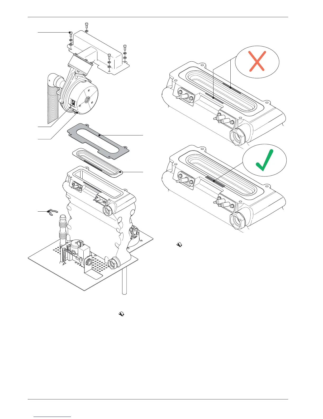
Burner installation
Ɣ Assemble the burner in reverse order to its removal.
– The burner surface and boiler body are marked in colour
(arrows) and may only b
e assembled where they match.
–
Pay attention to the stipulated tightening torque
(see chapter 12.3).
Ɣ Check the gas line for leakage.
Ɣ Start the burner. Check for function, leakage
at the burner
flange and the settings (see section 7.3.3).
1 Safety clamp
2 Mains plug, blower
3 Plug, blower controller
4 4x fixing screws (burner flange / boiler body)
5 Burner flange seal
6 Burner surface
Fig. 7-5 Removing the burner