7 Installation
Installer reference guide
20
RVLQ05+08CAV4 + RHYHBH05AA + RHYHBH/X08AA +
RHYKOMB33AA
ROTEX HPU hybrid
4P355635-1 – 2013.05
6.4.4 Overview of electrical connections for
external and internal actuators
Item Description Wires Maximum
running
current
Outdoor unit and indoor unit power supply
1 Power supply for
outdoor unit
2+GND
(a)
2 Power supply and
interconnection cable to
indoor unit
3+GND
(g)
3 Power supply gas
boiler
2+GND
(c)
4 Preferential kWh rate
power supply (voltage
free contact)
2
(e)
5 Normal kWh rate power
supply
2 6.3 A
User interface
6 User interface 2
(f)
Optional equipment
7 3-way valve 3 100 mA
(b)
8 Domestic hot water
tank thermistor
2
(d)
9 Power supply for drain
pan heater
2
(b)
10 Room thermostat 3 or 4 100 mA
(b)
11 Outdoor ambient
temperature sensor
2
(b)
12 Indoor ambient
temperature sensor
2
(b)
13 Heat pump convector 4 100 mA
(b)
Field supplied components
14 Shut-off valve 2 100 mA
(b)
15 Electricity meter 2
(b)
16 Domestic hot water
pump
2
(b)
17 Alarm output 2
(b)
18 Changeover to external
heat source control
2
(b)
19 Space cool/heat
operation control
2
(b)
20 Power consumption
digital inputs
2 (per input
signal)
(b)
21 Gas meter 2
(b)
(a) Refer to name plate on outdoor unit.
(b) Minimum cable section 0.75 mm².
(c) Use the cable supplied with the boiler.
(d) The thermistor and connection wire (12 m) are delivered
with the domestic hot water tank.
(e) Cable section 0.75 mm² till 1.25 mm²; maximum length:
50 m. Voltage-free contact shall ensure the minimum
applicable load of 15 V DC, 10 mA.
(f) Cable section 0.75 mm² till 1.25 mm²; maximum length:
500 m. Applicable for both single user interface and dual
use interface connection.
(g) Cable section 1.5 mm
2
; maximum length: 50 m.
NOTICE
More technical specifications of the different connections
are indicated on the inside of the indoor unit.
7 Installation
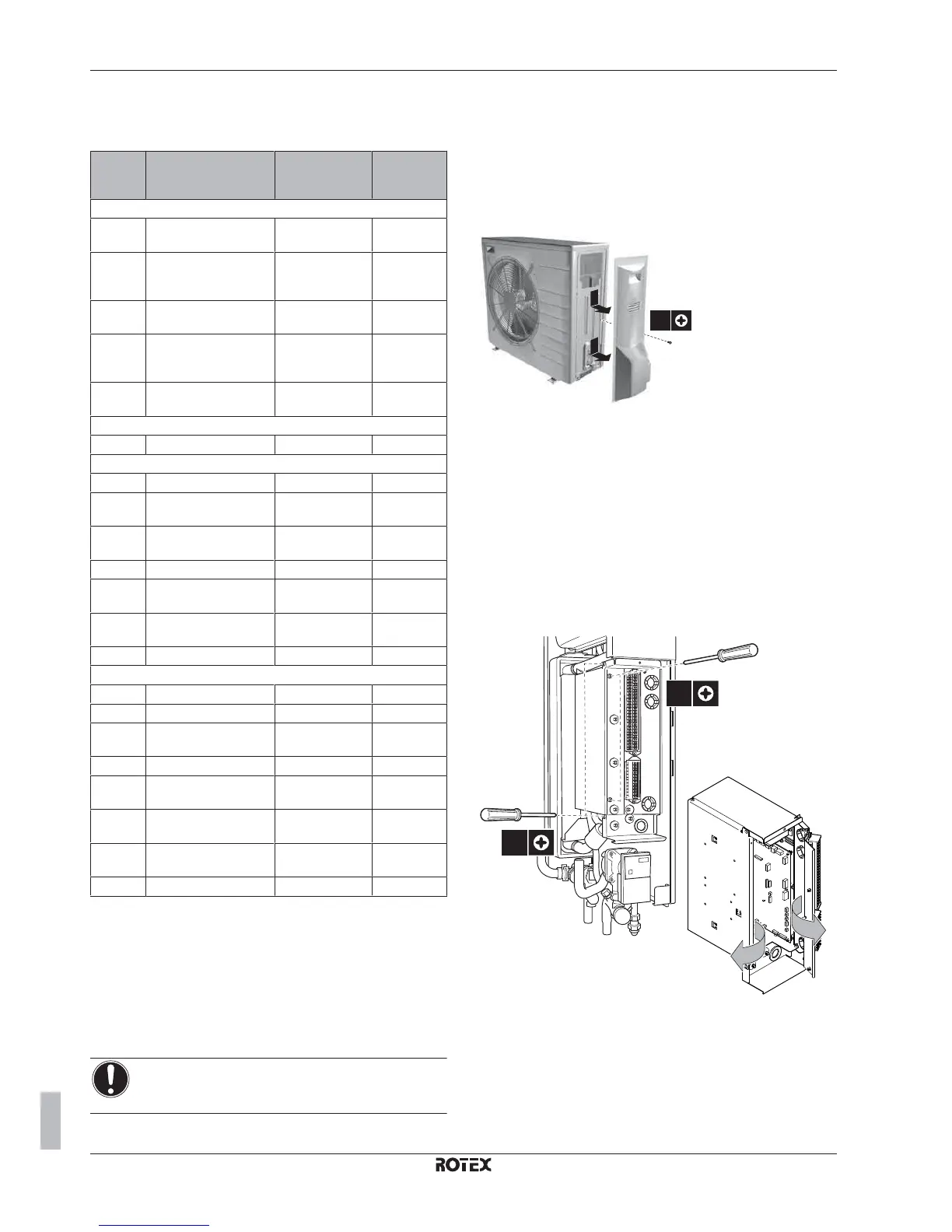
7.1 Opening the units
7.1.1 To open the outdoor unit
1 Remove 1 screw from the service cover.
1x
1
2
2
2 Remove the service cover.
7.1.2 To open the switch box cover of the
indoor unit
1 Remove the side panel at the right side of the indoor unit. The
side panel is fixed at the bottom with 1 screw.
2 Remove the upper and lower screw on the side panel of the
switch box.
3 The right panel of the switch box will open.
4 Remove the upper and lower screw on the front panel of the
switch box.
5 The front panel of the switch box will open.
2x
2x
2
4
5
3
When the boiler is installed and access to the switch box is required,
please follow the steps below.
6 Remove the upper and lower screw on the side panel of the
switch box.
7 Remove the switch box from the unit.
8 Hook the switch box to the side of the unit with the hooks
foreseen on the switch box.

 Loading...


