7 Installation
Installer reference guide
27
RVLQ05+08CAV4 + RHYHBH05AA + RHYHBH/X08AA +
RHYKOMB33AA
ROTEX HPU hybrid
4P355635-1 – 2013.05
NOTICE
Take the following precautions on refrigerant piping into
account:
▪ Avoid anything but the designated refrigerant to get
mixed into the refrigerant cycle (e.g. air).
▪ Only use R410A when adding refrigerant.
▪ Only use installation tools (e.g. manifold gauge set) that
are exclusively used for R410A installations to
withstand the pressure and to prevent foreign materials
(e.g. mineral oils and moisture) from mixing into the
system.
▪ Install the piping so that the flare is NOT subjected to
mechanical stress
▪ Protect the piping as described in the following table to
prevent dirt, liquid or dust from entering the piping.
▪ Use caution when passing copper tubes through walls
(see figure below).
Unit Installation period Protection method
Outdoor unit >1 month Pinch the pipe
<1 month Pinch or tape the pipe
Indoor unit Regardless of the
period
INFORMATION
Do NOT open the refrigerant stop valve before checking
the refrigerant piping. When you need to charge additional
refrigerant it is recommended to open the refrigerant stop
valve after charging.
Take the following guidelines into account when connecting pipes:
▪ Coat the flare inner surface with ether oil or ester oil when
connecting a flare nut. Tighten 3 or 4 turns by hand, before
tightening firmly.
▪ Always use two wrenches together when loosening a flare nut.
▪ Always use a spanner and torque wrench together to tighten the
flare nut when connecting the piping. This to prevent nut cracking
and leaks.
ab
c
d
a
Torque wrench
b
Spanner
c
Piping union
d
Flare nut
Piping size
(mm)
Tightening
torque (N•m)
Flare
dimensions
(mm)
Flare shape
(mm)
Ø6.4 15~17 8.7~9.1
R=0.4~0.8
45°
±2
90°
±2
A
Ø15.9 63~75 19.3~19.7
7.6.1 Pipe bending guidelines
Use a pipe bender for bending. All pipe bends should be as gentle
as possible (bending radius should be 30~40 mm or larger).
7.6.2 To flare the pipe end
CAUTION
▪ Incomplete flaring may cause refrigerant gas leakage.
▪ Do NOT re-use flares. Use new flares to prevent for
refrigerant gas leakage.
▪ Use flare nuts that are included with the unit. Using
different flare nuts may cause to refrigerant gas
leakage.
1 Cut the pipe end with a pipe cutter.
2 Remove burrs with the cut surface lacing downward so that the
chips does not enter the pipe.
ab
a
Cut exactly at right angles.
b
Remove burrs.
3 Remove the flare nut from the stop valve and put the flare nut
on the pipe.
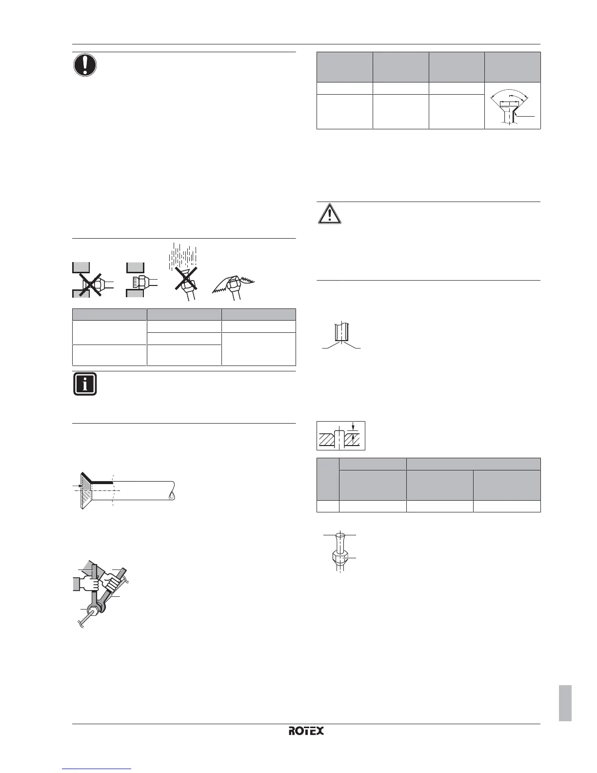
4 Flare the pipe. Set exactly at the position as shown in the
following illustration.
A
Conventional flare tool
Flare tool for
R410A (clutch
type)
Clutch type
(Ridgid-type)
Wing nut type
(Imperial-type)
A 0~0.5 mm 1.0~1.5 mm 1.5~2.0 mm
5 Check that the flaring is properly made.
a b
c
a
Flare’s inner surface must be flawless.
b
The pipe end must be evenly flared in a perfect
circle.
c
Make sure the flare nut is lifted.
7.6.3 To braze the pipe end
The indoor unit and outdoor unit have flare connections. Connect
both ends without brazing. If brazing should be needed, take the
following into account:
▪ When brazing, blow through with nitrogen to prevent creation of
large quantities of oxidised film on the inside of the piping. This
film adversely affects valves and compressors in the refrigerating
system and prevents proper operation.

 Loading...


