7 Installation
Installer reference guide
35
RVLQ05+08CAV4 + RHYHBH05AA + RHYHBH/X08AA +
RHYKOMB33AA
ROTEX HPU hybrid
4P355635-1 – 2013.05
7.8.5 To connect the main power supply of the
gas boiler
1 Connect the power supply cable of the gas boiler to a fuse (a)
(L: X2-2 (BRN), N: X2-4 (BLU)).
2 Connect the earthing of the gas boiler to an earthing terminal.
Result: The gas boiler performs a test.
appears on the service
display. After the test,
appears on the service display (wait mode).
The pressure in bar is shown on the main display.
a
X2
DANGER: RISK OF ELECTROCUTION
A fused spur or an unswitched socket MUST be located no
more than 1 m from the appliance.
CAUTION
For installation in damp rooms, a fixed connection is
obligatory. When working on the electrical circuit ALWAYS
isolate the electric supply.
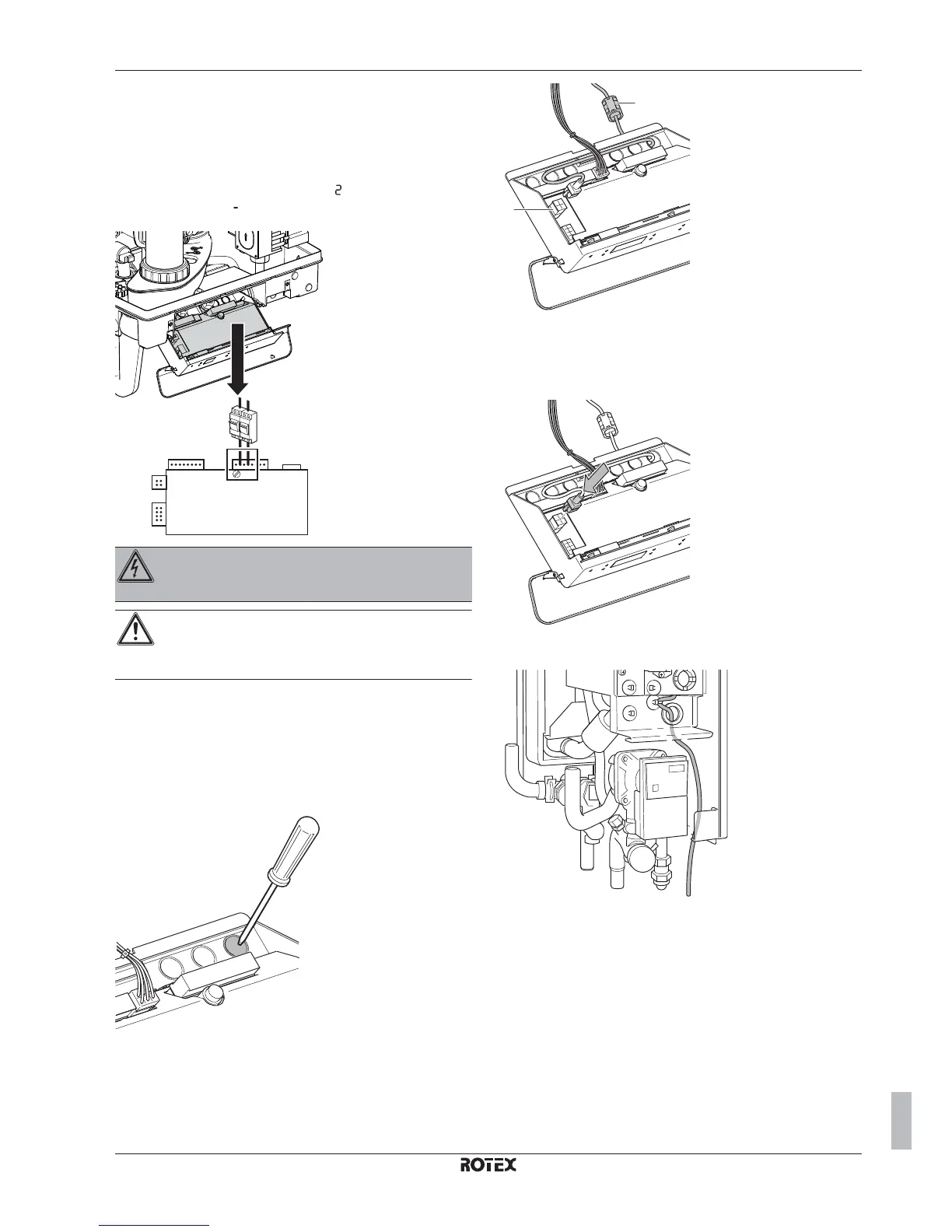
7.8.6 To connect the communication cable
between gas boiler and indoor unit
1 Open the gas boiler.
2 Open the switch box cover of the gas boiler.
3 Remove one of the bigger knockout holes on the right side of
the switch box of the gas boiler.
4 Put the (larger) boiler connector through the knockout hole. Fix
the cable in the switch box by routing it behind the pre-mounted
wires.
a
b
a
Solenoid coil
b
Connector X5
5 Plug the gas boiler connector into connector X5 of the gas
boiler PCB. Make sure the solenoid coil is outside the gas boiler
switch box.
6 Route the communication cable from the gas boiler to the
indoor unit as in figure below.
7 Open the switch box cover of the indoor unit.
8 Plug the indoor unit connector into X39A of the indoor unit PCB.

 Loading...


