16 Technical data
Installer reference guide
91
RVLQ05+08CAV4 + RHYHBH05AA + RHYHBH/X08AA +
RHYKOMB33AA
ROTEX HPU hybrid
4P355635-1 – 2013.05
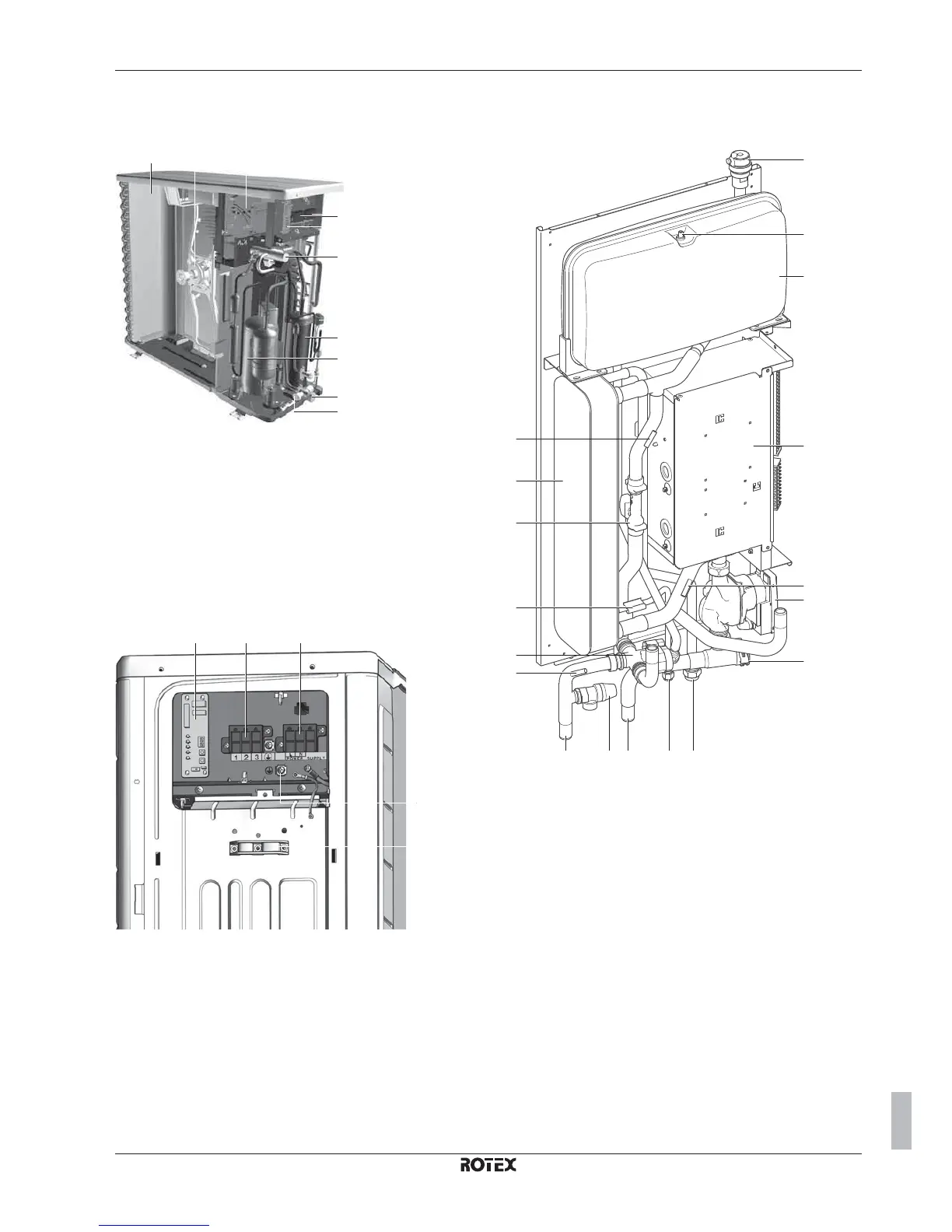
16.2 Components
16.2.1 Components: Outdoor unit
b
c
d
e
f
j
h
i
g
alk
a
Switch box main PCB (inverter and control PCB)
b
Terminal communication and power supply
c
Service PCB
d
4-way valve
e
Electronic expansion valve (main)
f
Accumulator
g
Compressor
h
Liquid stop valve
i
Gas stop valve
j
Service port
k
Fan motor
l
Heat exchanger
16.2.2 Components: Switch box (outdoor unit)
ac
d
e
b
a
Service PCB
b
Terminal communication cable
c
Terminal power supply cable
d
Earth connection
e
Wire clamp
16.2.3 Components: Indoor unit
a
f
m
g
h ijkl
b
c
n
d
m
m
o
m
e
a
Switch box
Contains the main electronic and electrical parts of the
indoor unit.
b
Air purge valve
Remaining air in the water circuit will be automatically
removed via the air purge valve.
c
Expansion vessel (10 l)
d
Flow sensor
Gives feedback to the interface about the actual flow. Based
on this information (and other), the interface adjusts the
pump speed.
e
Heat exchanger
f
Water pump
Circulates the water in the water circuit.
g
Water filter
Removes dirt from the water to prevent damage to the pump
or blockage of the heat exchanger.
h
Pressure relief valve
Prevents excessive water pressure in the water circuit by
opening at 3 bar.
i
Refrigerant gas connection R410A
j
Refrigerant liquid connection R410A
k
Water inlet connection
l
Water outlet connection

 Loading...


