7 Installation
Installer reference guide
33
RVLQ05+08CAV4 + RHYHBH05AA + RHYHBH/X08AA +
RHYKOMB33AA
ROTEX HPU hybrid
4P355635-1 – 2013.05
7.8.1 About electrical compliance
Only for RVLQ08CAV3
Equipment complying with EN/IEC 61000-3-12 (European/
International Technical Standard setting the limits for harmonic
currents produced by equipment connected to public low-voltage
systems with input current >16 A and ≤75 A per phase.).
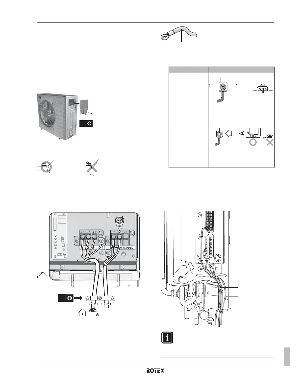
7.8.2 To connect the electrical wiring on the
outdoor unit
1 Remove the 2 switch box cover screws.
2 Remove the switch box cover.
2x
1
1
2
3 Strip insulation (20 mm) from the wires.
ab
a
Strip wire end to this point
b
Excessive strip length may cause electrical shock
or leakage.
4 Open the wire clamp.
5 Connect the interconnection cable and power supply as follows:
3x
123
6 Install the switch box cover.
▪ If stranded conductor wires are being used, install a round crimp-
style terminal on the tip. Place the round crimp-style terminal on
the wire up to the covered part and fasten the terminal with the
appropriate tool.
ba
a
Stranded conductor wire
b
Round crimp-style terminal
▪ Use the following methods for installing wires:
Wire type Installation method
Single core wire
cb
c
a
a
A
AA´
A´
a Curled single core wire
b Screw
c Flat washer
Stranded conductor
wire with round crimp-
style terminal
cb bac
a
B
B
a Terminal
b Screw
c Flat washer
7.8.3 To connect the electrical wiring on the
indoor unit
It is recommended to install all electrical wiring to the hydro box
before installing the boiler.
1 Wiring should enter the unit from the bottom.
2 Routing of the wiring inside the unit should be as follows:
b
a
c
a
b
c
INFORMATION
When installing field supply or option cables, foresee
sufficient cable length. This will make it possible to remove/
reposition the switch box and gain acces to other
components during service.

 Loading...


