7 Installation
Installer reference guide
41
RVLQ05+08CAV4 + RHYHBH05AA + RHYHBH/X08AA +
RHYKOMB33AA
ROTEX HPU hybrid
4P355635-1 – 2013.05
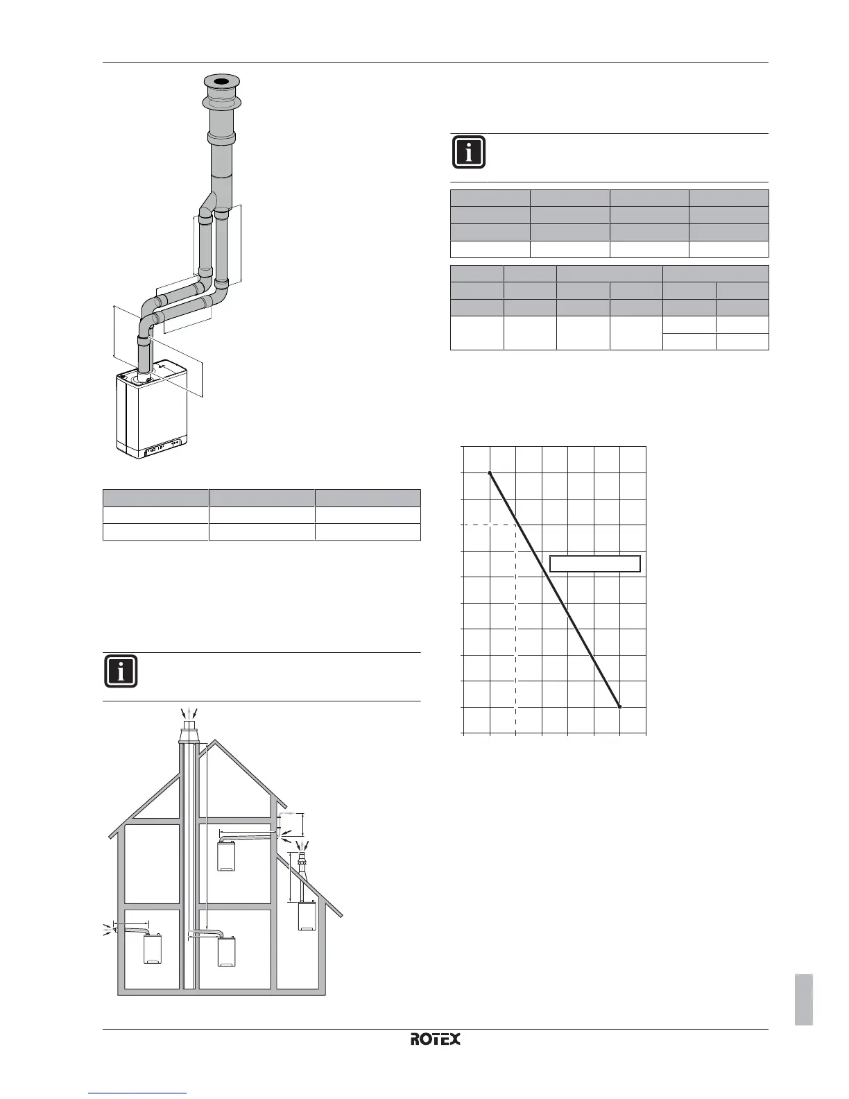
L6
L4
L3
L1
L2
L5
Sample calculation for dual pipe application
Pipe Pipe length Total pipe length
Flue pipe L1+L2+L3+(2×2) m 13 m
Air supply L4+L5+L6+(2×2) m 12 m
Total piping length = sum of the straight pipe lengths + sum of the
equivalent pipe length of bends/elbows.
7.10.4 Appliance categories and pipe lengths
Following installation methods are supported by the manufacturer.
Single boiler installation
INFORMATION
All piping lengths in the tables below are maximum
equivalent piping lengths.
1
L1
L1
L2
L1
3
2
C
53
C
93
C
13
C
33
L2
4
L1
The horizontal flue MUST be installed under a 3° fall towards the
boiler (50 mm per meter) and MUST be supported with a minimum
of 1 bracket at each meter length. Best recommended position of the
bracket is just before the joint.
INFORMATION
Flexible flue gas lines may NOT be used in horizontal
connection sections.
C
13
(1) C
33
(2) C
13
(1) C
33
(2)
60/100 60/100 Twin-80 Twin-80
L1 (m) L1 (m) L1 (m) L1 (m)
10 10 80 21
C
13
(1) C
33
(2) C
93
(4) C
53
(3)
80/125 80/125 80/125 80 60/100 60
L1 (m) L1 (m) L1 (m) L2 (m) L1 (m) L2 (m)
29 29 10 25 6 1
1 10
Special remark regarding C
53
: The maximum lengths for L1 and L2
are related to each other. First determine the length of L1; then
make use of the graph below to determine the maximum length of
L2. For example: if the length of L1 is 2 m, L2 can maximally be 8 m
long.
7
6
5
10
9
11
8
3
4
2
1
0
L2
L1
01234 675
L2=–1.8×L1+11.8

 Loading...


