16 Technical data
Installer reference guide
99
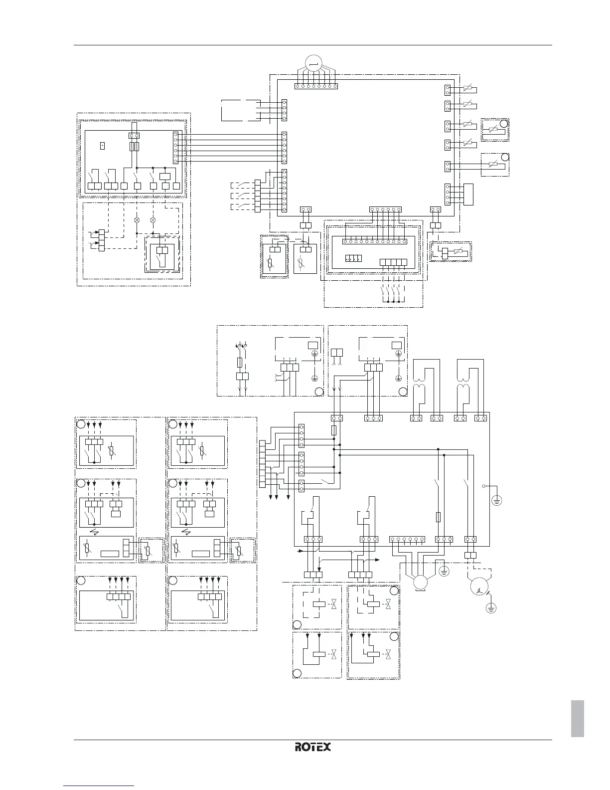
RVLQ05+08CAV4 + RHYHBH05AA + RHYHBH/X08AA +
RHYKOMB33AA
ROTEX HPU hybrid
4P355635-1 – 2013.05
4D082241 page 4
X6A:1
2
2
R3T
-t°
2
X5A:1
2
R2T
-t°
X8A:1
X7A:1
R4T
-t°
X9A:1
2
R5T
-t°
5
6
4
3
2
X40A:1
10 11 129876543
5
6
4
3
X33A:1
3
2
X4A:1
8
7
2
X80A:1
S6S
S7S
S8S
S9S
R1T
-t°
6
5
4
32
X85A:1 X22A:1
2
X18A:1
2
R1T
-t°
R1T
-t°
2
R6T
-t°
R5T
-t°
S1S
S2S
S3S
CN2:1
2
3
4
5
6
CN1:1 3
F2U
F1U
BSK
KFRKCR
KHURKHR
M
M4S
X70A:1
2 3 5 64 7 8
4
3
X39A:1
2
4
X24A.5
X2M.9
B1L
5 6 X5M
A8P
12
X801M
345
DS1
1234
3
X5M
4
9
10
1
2
A2P
12
X5M
P1 P1 P2P2
A2P
A1P
7
8
A4P
SS1
12
A3P
13a
X2M
21
28
29
X1 X2 X3 X4 Y3 Y4YC Y2Y1
PHC1
(*)
0.3 A - 250 V AC
20 mA - 5 V DC
4
4
*HYKOMB*
User interface
X5
Switch box
Options: solar pump connection, alarm output, On/OFF output
Only for digital I/O PCB option
Digital I/O PCB
GAS BOILER
Max. load
Min. load
Power limitation
digital inputs:
12 V DC / 12 mA detection
(voltage supplied by PCB)
ON
OFF
Demand PCB
Only for demand PCB option
ext. ambient
sensor option
(indoor or
outdoor)
only for instant hot water
(recirculation) without tank
only for domestic
hot water tank option
Remote
user interface
Switch box
Gas pulse meter input:
5 V DC pulse detection
(voltage supplied by PCB)
Electric pulse meter input:
5 V DC pulse detection
(voltage supplied by PCB)
Preferential kWh rate PS contact:
16 V DC detection
(voltage supplied by PCB)
Space C/H
On/OFF output (*)
Alarm
output (*)
ON
OFF
only for solar option
6
5
4
32
X25A:1
MS
3~
M1P
X16A:5
1
3
X17A:1
3
5
7
X24A:1
3
5
7
Q1DI
1
X1A:3 X19A:1
3 5
X6YA
X6Y
X6YB
X6YA
X6Y
X6YB
FU1
X26A:1
2
X31A:1
3
TR1
X20A:1
3
5
X2A:1
KCR
M
1~
M2P
X15A:1
3
E
X14A:1
3
R1T
-t°
R1T
-t°
R2T
-t°
K4R
KPR
FU2
KVR
R1T
-t°
R1T
-t°
R2T
-t°
K6R
3
5
M2S
M2S
X27A:1
2
X30A:1
3
TR2
M3S
M3S
X2M.4
X2M.3
X2M.1
X2M.2
X2M.3
X2M.2
X2M.4
X2M.1
X2M.4
X2M.1a
X2M.2a
X2M.3
X2M.2a
X2M.4
X2M.1a
X2M.4
X2M.32
X2M.33
X2M.4
X2M.32
X2M.33
X2M.1a
X2M.4
X2M.7
X2M.1
X2M.28
X2M.13a
X2M.8
X2M.9
X2M.10
X2M.7
X2M.8
X2M.5
A1P
PE
N
L
GND
PWM
NL
1N~, 50 Hz
230 V AC
1
213
123
X2M
3130
1
213
123
X1M
X2M
30 31
X1M
567
3
3
X2M
34
X2M
35
COM
HC
H
COM
C
L
PC
N
5
5
5
6543
A3P
X11M
X1M
A3P
A4P
A3P
COM
HC
H
COM
C
only for wireless
On/OFF thermostat
L
PC
N
6
6
6
65
A3P
X11M
X1M
A3P
A4P
A3P
3
4
32
33
2a
1a
2
1
%H20
%H20
34
X2M
R1H
R1H
X1M
X1M
10
9X2M 8
8a
N
L
NC
N
2
2
NO
4D082241 page 5
only for ext.
sensor
(floor or
ambient)
only for ext.
sensor
(floor or
ambient)
only for wireless
On/OFF thermostat
Only for preferential kWh rate power supply (outdoor)
Use normal kWh rate power supply for indoor unit
Only for normal power supply (standard)
Indoor unit supplied from outdoor
only for domestic
hot water tank option
Shut-off valve
only for wired On/OFF thermostat only for wired On/OFF thermostat
Normal kWh rate
power supply
OUTDOOR
UNIT
OUTDOOR
UNIT
Switch box
NC valve
NO valve
3 wire type
(SPDT)
DHW pump output
Max. load:
2 A (inrush) - 230 V AC
1 A (continuous)
Heatpump convector
Main LWT zone
Heatpump convector
Add LWT zone
3 wire type
(SPST)

 Loading...


