VM1000 Series
‐60‐
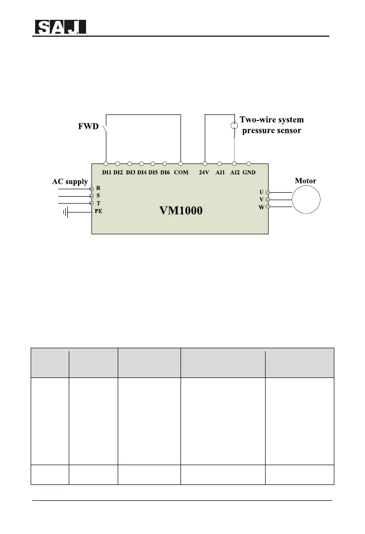
(2)Typical wiring
The following the water supply system wiring diagram that adopts given digital and
analog feedback
Figure 4-4 VM1000 PID Control
(3) Parameters setting
This control application is terminal control, which start and stop is 2-wire or 3-wire.
The master frequency needs to be modified as PID. Part of the control parameters
can be found in the above Table 4-4. The following Table 4-7 is the PID para
example in Figure 4-4 that adopts AI2 analog feedback.
Function
code
Name Setting Instruction Notes
F0.03
Master
Frequency
Reference X
Selection
0: Eletronic
potentiometer
(non-retentive at
power off)……
8:PID
9:Communication
given
Modify the setting as 8;
adopt PID output as
master frequency
reference
F5.23
AI2 lower
0.00V ~ F5.20
Setting according to the Used for checking
M