SAM4S ER-5200 Series 7-1
7 Special Circuit Descriptions
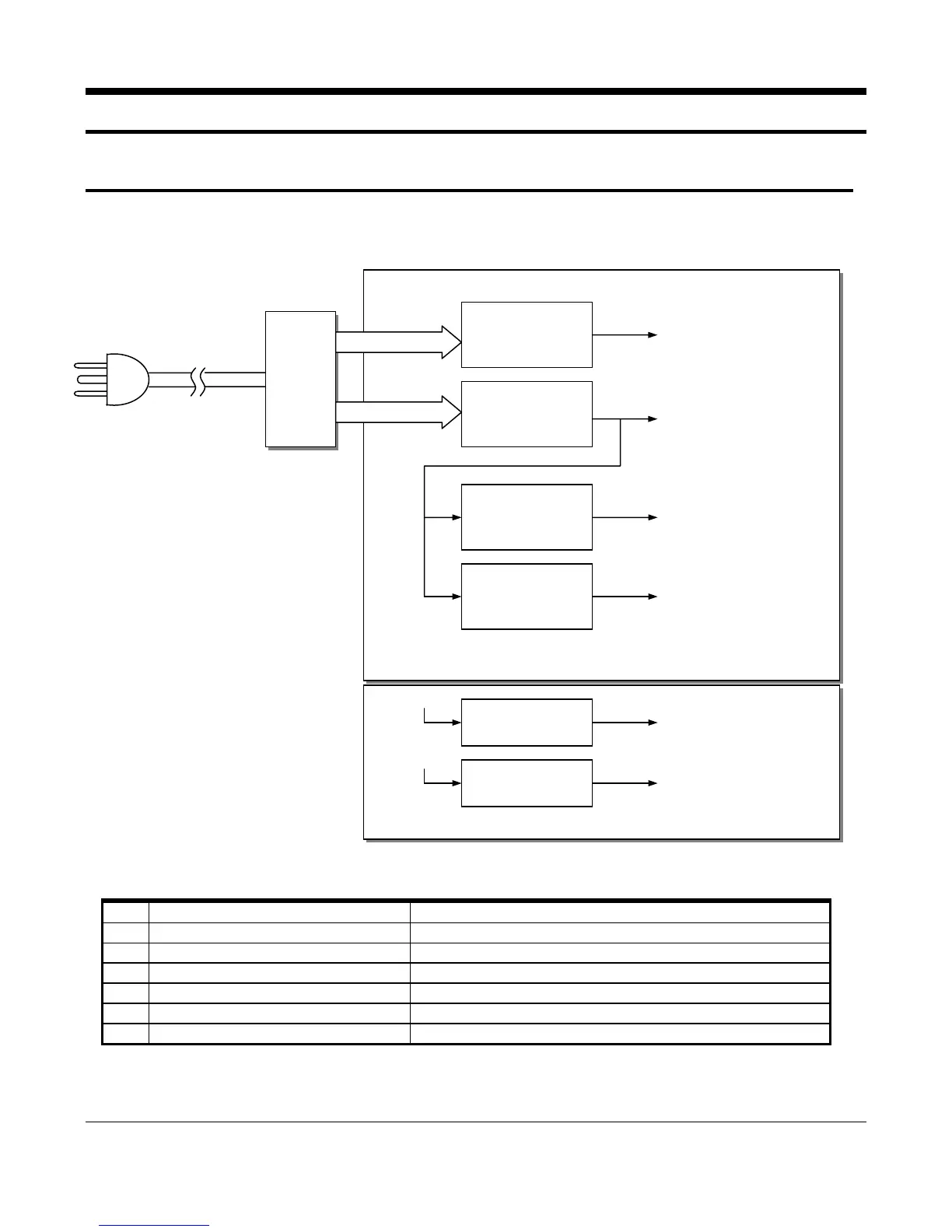
7-1 Power Circuit
This system is operated under 120Vac or 230Vac. All data is saved by the Battery when the Main power is turned off.
The power circuit supplies the five different DC voltage sources and one AC voltage source.
Figure 7-1 Power Block Diagram
No. Voltage Description
1 VDISP (+30VDC) VFD Grid/Anode Driving Voltage
2 VDRV (+24VDC) Cash Drawer Solenoid Driving / Fiscal Writing Voltage
3 VCC (+5VDC) Logic IC Driving / VFD Filament Voltage
4 VPRT (+8.5VDC) Thermal Printer Step Motor, A/Cut Motor Driving Voltage
5 VPH (+8.5VDC) Thermal Printer Head Driving Voltage
6 VBT (+Min 3.6VDC) Battery Voltage
Table 7-1 Power Source Voltage Descriptions
POWER
TRANS
Power
Rectification
Circuit #1
VDISP(+30V)
VDRV(+24V)
POWER PWB
Power
Rectification
Circuit #1
[For Drawer, Fiscal Volt.]
[Power Fail Source]
[For VFD Display]
Voltage
Regulation
Circuit #2
VPRT(+8.5V)
[For Printer LF Motor]
[For Auto Cut Motor]
[For Spool Motor]
[For VPH Source]
Voltage
Regulation
Circuit #1
VCC(+5V)
[For Logic, VFD]
MAIN PWB
TPH Supply Volt.
On/Off Circuit
VPRT(+8.5V)
VPH(+8.5V)
[For TPH Voltage]
Battery Volt.
Storage Circuit
VCC(+5.0V)
VBT(+Min 3.6.V)
[For Battery Voltage]
 Loading...