7 Special Circuit Description
SAM4S ER-5200 Series 7-9
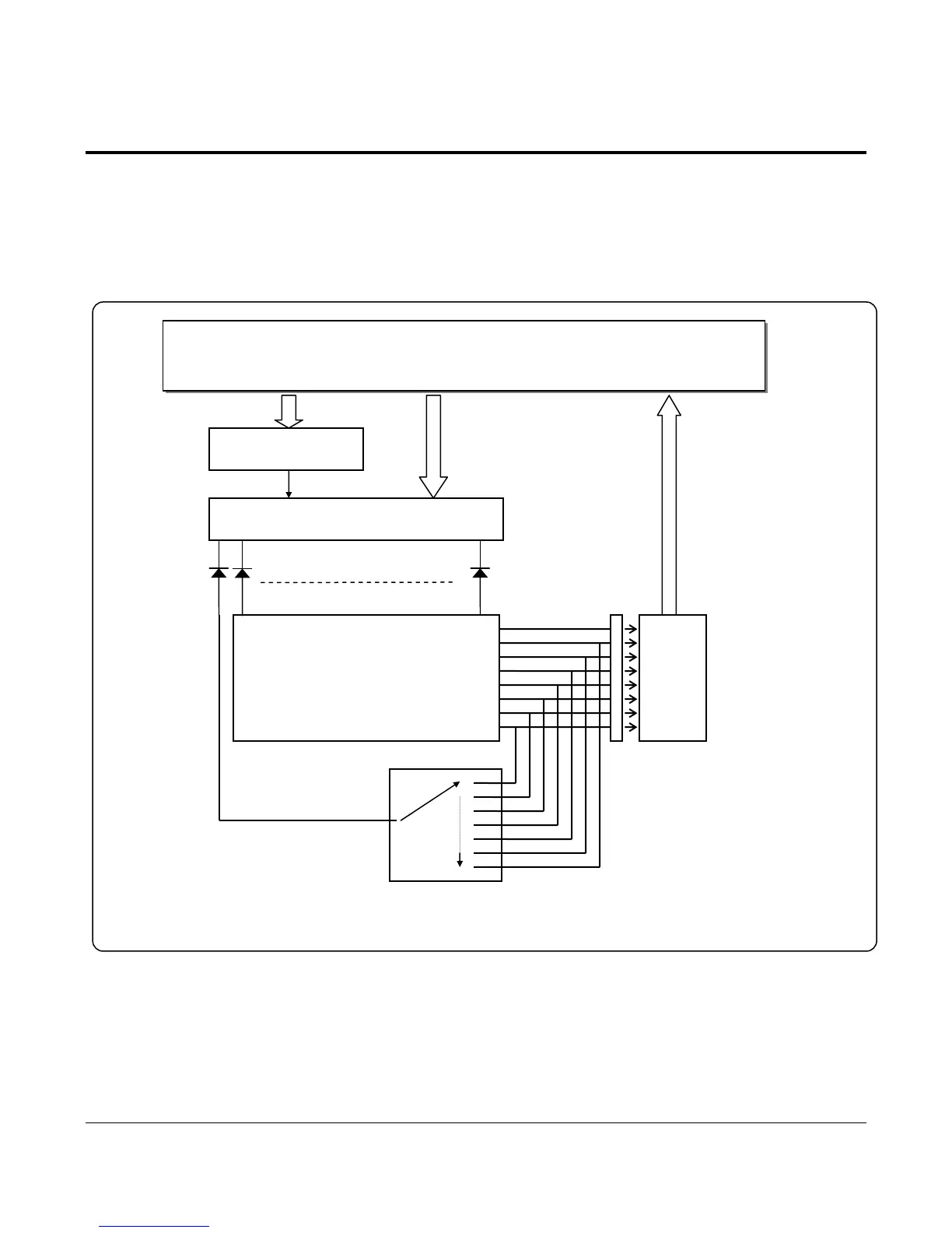
7-6 Keyboard Circuit
The Key Board Circuit consist of the scan signal of 20 lines and the return signal of 8-line. The CPU sends repeatedly and
continuously the scan data S0 S∼ 19 through the 74HCT138(U16,U18,U23). The key information input in the return
signal if the specific key is pressed during the given time. The CPU reads the data through U27(74HC541) and analyzes
what key is pressed and transmits this information to the CPU, then performs the selected function. The Key Board Circuit
sends the mode scan signal to the Key-lock switch and takes the return data through the U27(74HC541) and performs the
selected function.
Figure 7-13 Keyboard Block Diagram
DATA[0:7]
74HCT541
(U27)
ADDR[0:5]
CPU (M30800SFP)
160 KEYS
Pull-Up
COMMON PORT
•
•
•
•
•
•
•
MODE KEY
•
•
•
•
•
•
•
•
ADDRESS DECODER(74HC138)
( U16, U18, U23 )
DIODE( MMBD6050L *20)
ADDRESS DECODER
(74HC138,U21)
CS1, ADDR[11:13], nRESET
KBD_CS
 Loading...