EB 8384-2 EN 79
Mounting and start-up
5.12 Retrotting an inductive
limit switch
Required retrot kit:
Limit switch Order no. 1402-1770
The same requirements apply to retrotting a
unit as to servicing the positioner. For explo-
sion-protected positioners, the requirements
in Servicing explosion-protected devices
need to be kept. Check the "Limit switch, in-
ductive" box on the nameplate after install-
ing the limit switch.
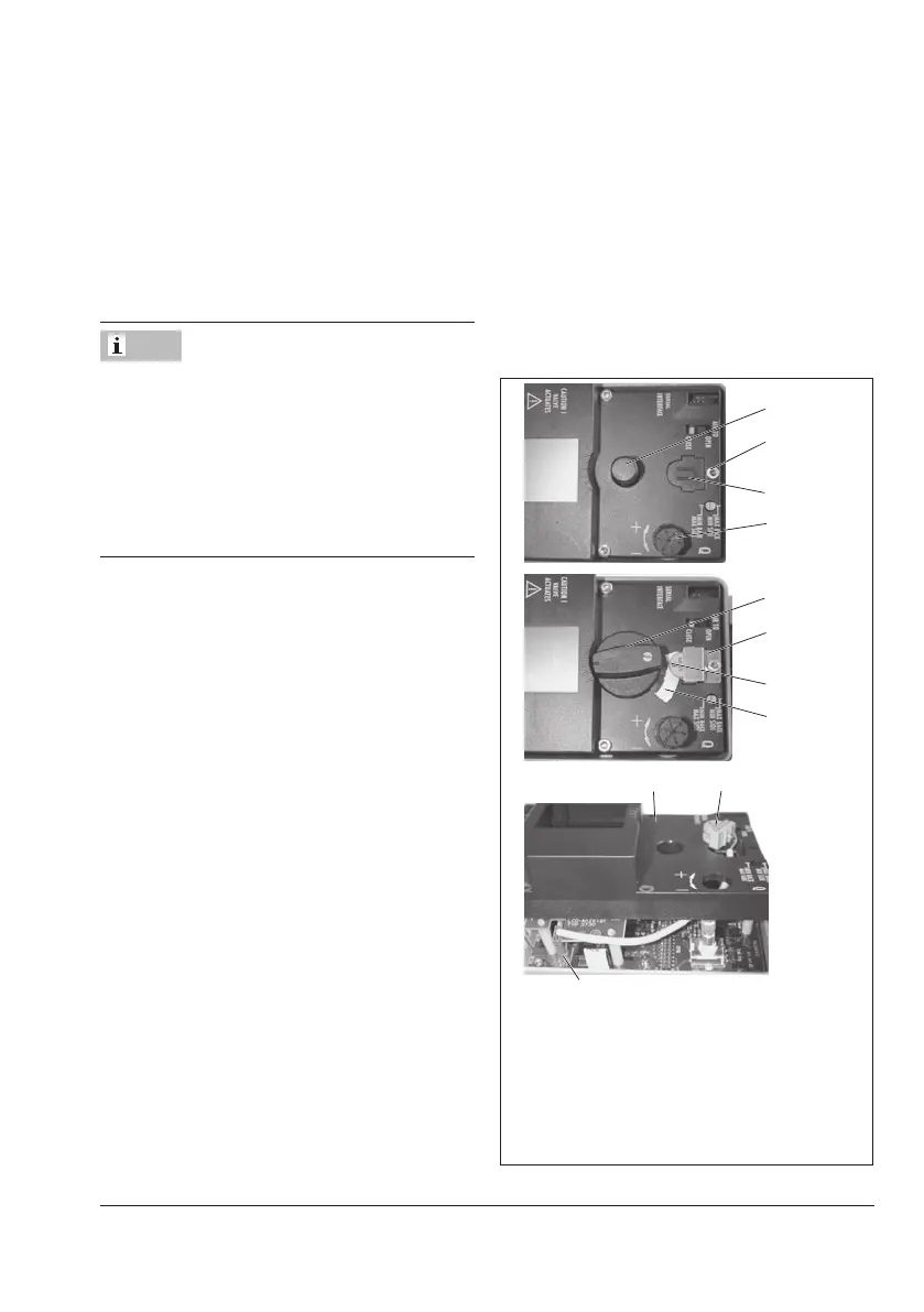
1. Take off the rotary pushbutton (3) and cap
(1),unthreadthevefasteningscrews(2)
and lift off the plastic cover (9) together
with the display, taking care not to dam-
age the ribbon cable (between PCB and
display).
2. Use a knife to cut an opening at the
marked location (4).
3. Push the connector (11) with cable
through the opening and secure the prox-
imity switch (7) on the cover with a dot of
glue.
4. RemovethejumperatthesocketX7ofthe
top board and insert the cable connector
(11).
5. Guide the cable in such a manner that the
plastic cover can be placed back onto the
positioner.Insertthexingscrews(2)and
screw tight. Attach the clamping plate (8)
onto the proximity switch.
6. Attach the rotary switch (5). Make sure
theattenedsideofthepositionershaftis
turned so that the rotary switch (5) can be
attached with the metal tag next to the
proximity switch.
7. On start-up of the positioner, set the op-
tioninductivealarmunderCode38from
No to YES.
1
2
3
4
5
8
6
7
9
7
Socket X7 (11)
1 Cap 6 Metal tag
2 Screw 7 Proximity switch
3 Rotarypushbutton 8 Clamping plate
4 Marking 9 Plastic cover
5 Rotaryswitch 11 Connector
Fig.31: Retrotting an inductive limit switch
Note
 Loading...


