88 EB 8384-2 EN
Mounting and start-up
5.16.1 Connecting the electrical power
Risk of malfunction due to incorrect sequence of mounting, installation and start-up.
Keep the following sequence.
1. Remove the protective caps from the pneumatic connections.
2. Mount the positioner on the valve.
3. Connect the supply air.
4. Connect the electrical power.
5. Perform settings.
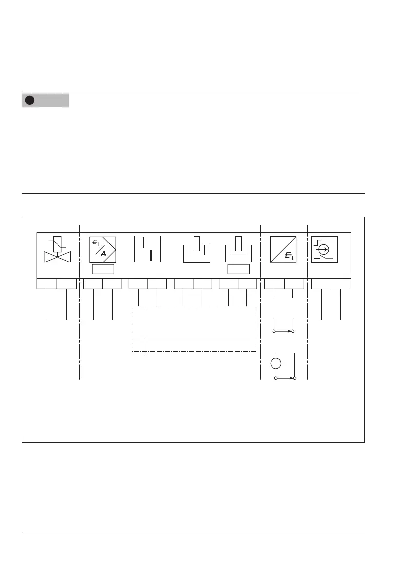
Î Connecttheelectricalpower(mAsignal)asshowninFig.33.
G
+81 -82 +11 -12
+83
-84 +51
-52
A2A3 A1
+41 -42
+31 -32
A
+31 -32
No
ex
BinaryinputofaPLCacc.toIEC61131-2
(P
max
=400mW)orswitchingamplier
acc.toEN60947-5-6
Ex
Switchingamplieraccordingto
EN60947-5-6
Optional
Optional Optional
24VDC
Solenoid valve
(optional)
mA
control signal
A3
Fault alarm
A2
Software
A1
Software
optionally inductive
Limit switches
Leakage
sensor
Position transmitter
with two-wire
transmitter supply
unit
Binary input
Fig.33: Electrical connections
NOTICE
!
 Loading...


