EB 8384-2 EN 75
Mounting and start-up
5.10.2 Mounting the position
sensor with attachment
according to
IEC60534-6
Î Requiredmountingpartsandaccesso-
ries:Table8onpage27.
Î RefertoFig.27
1. Place the lever (1) on the position sensor
in mid-position and hold it in place. Un-
thread the nut (1.1) and remove the lever
together with the disk spring (1.2) from
the sensor shaft.
2. Screw the position sensor (20) onto the
bracket (21).
The standard attached M lever with the fol-
lower pin (2) at position 35 is designed for
120to350cm²actuatorswith15mmrated
travel. For other actuator sizes or travels, se-
lect the lever and pin position from the travel
tableonsection3.5.1.LandXL levers are
included in the mounting kit.
3. Place the lever (1) and disk spring (1.2)
on the sensor shaft. Place the lever in
mid-position and hold it in place. Screw
on the nut (1.1).
4. Screw the two bolts (14) to the bracket
(9.1) of the stem connector (9), place the
follower plate (3) on top and use the
screws (14.1) for fastening.
5. Place the bracket with the sensor at the
NAMURribinsuchamannerthatthe
follower pin (2) rests in the slot of the fol-
lower plate (3), then screw the bracket
usingitsxingscrewsontothevalve.
2
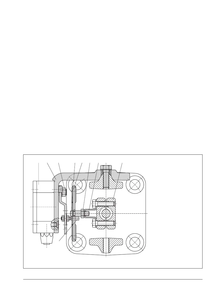
1 Lever
1.1 Nut
1.2 Disk spring
2 Follower pin
3 Follower plate
9 Stem connector
9.1 Bracket
14 Bolt
14.1 Screws
20 Position sensor
21 Bracket
Fig.27: Mounting according to IEC60534-6 (NAMUR)
 Loading...


