72 EB 8384-2 EN
Mounting and start-up
Pressure gauge attachment
ThemountingsequenceshowninFig.24re-
mains unchanged. Screw a pressure gauge
bracket onto the connections A
1
and Z.
Pressure gauge
bracket
G¼ 1400-7106
¼NPT 1400-7107
Pressure gauges for supply air Z and output
A
1
aslistedinTable8toTable9.
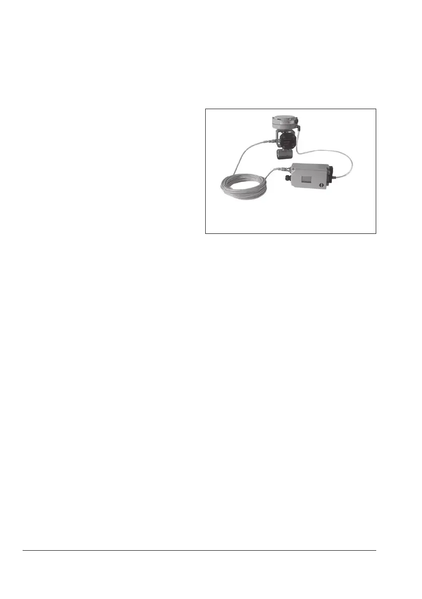
5.10 Attachment of external
position sensor
Fig.25: Positioner unit with sensor mounted on
a micro-ow valve
Î Requiredmountingpartsandaccesso-
ries:Table8onpage27.
In the positioner version with an external
position sensor, the sensor located in a
separate housing is attached over a plate or
bracket to the control valve. The travel pick-
off corresponds to that of a standard device.
The positioner can be mounted as required
to a wall or a pipe.
For the pneumatic connection either a con-
necting plate (6) or a pressure gauge brack-
et(7)mustbexedtothehousing,depend-
ing on the accessory chosen. Make sure the
seals(6.1)arecorrectlyinserted(seeFig.9,
bottom right).
For the electrical connectiona10meter
connecting lead with M12x1 connectors is
included in the scope of delivery.
 Loading...


