EB 8384-2 EN 77
Mounting and start-up
20
21
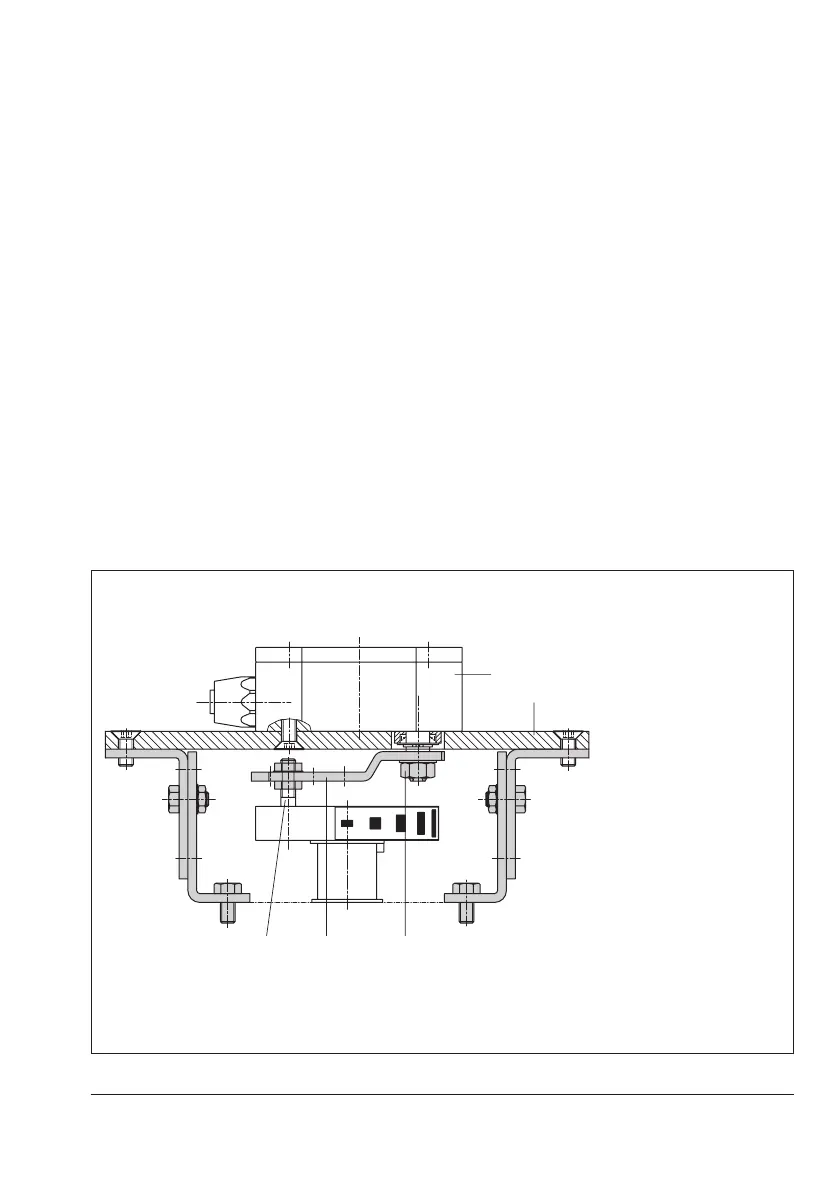
1 Lever
1.1 Nut
1.2 Disk spring
2 Follower pin
20 Position sensor
21 Mounting plate
Fig.29: Mounting on rotary actuators
5.10.4 Mounting on rotary ac-
tuators
Î Requiredmountingpartsandaccesso-
ries:Table8onpage27.
Î RefertoFig.29
1. Place the lever (1) on the position sensor
in mid-position and hold it in place. Un-
thread the nut (1.1) and remove the lever
together with the disk spring (1.2) from
the sensor shaft.
2. Screw the position sensor (20) onto the
mounting plate (21).
3. Replacethefollowerpin(2)normallyat-
tached to the lever (1) with the metal fol-
lowerpin(Ø5mm)fromtheaccessories
and screw it into the hole for pin position
90°.
4. Place the lever (1) and disk spring (1.2)
on the sensor shaft. Place the lever in
mid-position and hold it in place. Screw
on the nut (1.1).
Follow the instructions describing attachment
tothestandardpositionerinsection5.8.
Instead of the positioner, attach the position
sensor (20) with its mounting plate (21).
 Loading...


