EB 8384-2 EN 83
Mounting and start-up
5.15 Pneumatic connections
Risk of injury by possible movement of ex-
posed parts (positioner, actuator or valve)
after connecting the signal pressure.
Do not touch or block exposed moving parts.
Incorrect connection of the supply air will
damage the positioner and will lead to mal-
function.
Screw the screw ttings into the connecting
plate, pressure gauge mounting block or
connection block from the accessories.
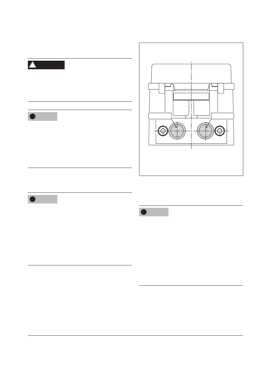
The pneumatic ports are located on the back
ofthepositioner(seeFig.32).
Risk of malfunction due to failure to comply
with required air quality.
Only use supply air that is dry and free of oil
and dust.
Read the maintenance instructions for up-
stream pressure reducing stations.
Blow through all air pipes and hoses thor-
oughly before connecting them.
Supply 9Output 38
Supply 9
Output 38
Fig.32: Pneumatic connections
5.15.1 Connecting the supply
air
Risk of malfunction due to incorrect sequence
of mounting, installation and start-up.
Keep the following sequence.
1. Remove the protective caps from the
pneumatic connections.
2. Mount the positioner on the valve.
3. Connect the supply air.
4. Connect the electrical power.
5. Perform settings.
WARNING
!
NOTICE
!
NOTICE
!
NOTICE
!
 Loading...


