66 EB 8384-2 EN
Mounting and start-up
2. Placecouplingwheel(4)withatside
facing the actuator on the follower clamp
(3).RefertoFig.22toalignslotsothatit
matches the direction of rotation when
the valve is in its closed position.
3. Fasten the coupling wheel (4) and follow-
er clamp (3) tightly onto the actuator
shaft using screw (4.1) and disk spring
(4.2).
4. Fasten the bottom pair of brackets (10.1)
with the bends pointing either facing to
the inside or to the outside (depending
on the actuator size) onto the actuator
housing. Position the top pair of brackets
(10) and fasten.
5. Mount connecting plate (6) or pressure
gauge bracket (7) with pressure gauges
on the positioner, making sure the two
seals are seated properly. Double-acting
springless rotary actuators require the
useofareversingamplieronthecon-
nection side of the positioner housing
(seesection5.9).
6. Unscrew the standard follower pin (2)
from the positioner's M lever (1). Use the
metalfollowerpin(Ø5mm)includedin
the mounting kit and screw tight into the
hole for pin position 90°.
7. Place positioner on the top bracket (10)
and fasten tight. Taking the actuator's di-
rection of rotation into account, adjust le-
ver (1) so that it engages in the slot of
the coupling wheel (4) with its follower
pin(Fig.22).Itmustbeguaranteedthat
the lever (1) is parallel to the long side of
the positioner when the actuator is at
half its angle of rotation.
8. Stick the scale plate (4.3) on the coupling
wheel so that the arrow tip indicates the
closed position and it can be easily read
when the valve is installed.
5.8.1 Heavy-duty version
Î RefertoFig.23
Î Requiredmountingpartsandaccesso-
ries:Table7onpage26.
Both mounting kits contain all the necessary
mounting parts. The parts for the actuator
size used must be selected from the mount-
ing kit.
Prepare actuator and mount possibly re-
quired adapter supplied by the actuator
manufacturer.
1. Mount the housing (10) onto the rotary
actuator.IncaseofVDI/VDEattachment,
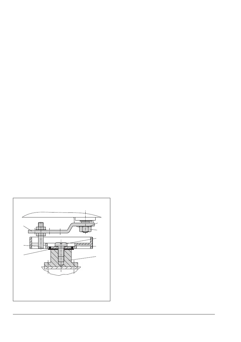
1
2
4.2
5
Fig.20: Mounting the coupling wheel on
Type3278
Legend for Fig.20 and Fig.21
1 Lever
1.1 Nut
1.2 Disk spring
2 Follower pin
3 Follower clamp
4 Coupling wheel
4.1 Screw
4.2 Disk spring
4.3 Scale plate
5 Actuator shaft
AdapterforType3278
6 Connecting plate
6.1 Seals
7 Pressure gauge bracket
8 Pressure gauge mounting kit
10 Top pair of brackets
10.1 Bottom pair of brackets
10
10.1
6
(7, 8)
1.1
2
4.3
5
6.1
4
1.2
1
130 mm
80 mm
NOTICE
Only use the connecting
plate (6) included in the ac-
cessories to connect supply
and output.
Never screw threaded parts
directly into housing.
Control valve opens counterclockwise
Control valve opens clockwise
Slot
Slot
Fig.21: Attachment to rotary actuators
 Loading...


