EB 8384-2 EN 69
Mounting and start-up
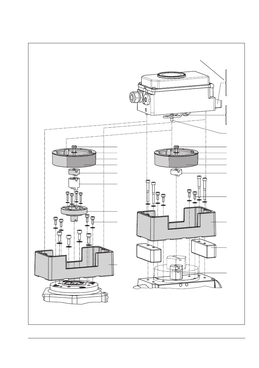
place spacers (11) underneath, if neces-
sary.
2. For SAMSONType3278andVETEC
S160 Rotary Actuators, fasten the
adapter (5) onto the free end of the shaft
and for VETECR Actuator, place on the
adapter (5.1). For Type3278, VE-
TECS160 and VETECR Actuators, place
on the adapter (3), for VDI/VDE version,
only use the adapter when it is required
due to the actuator size.
3. Stick adhesive label (4.3) onto the cou-
pling in such a manner that the yellow
part of the sticker is visible in the window
of the housing when the valve is OPEN.
Adhesive labels with explanatory sym-
bols are enclosed and can be stuck on
the enclosure, if required.
Actuator turning
counterclockwise
Actuator turning
clockwise
Fig.22: Direction of rotation
6
6.1
7
8
1
1.1
1.2
2
4.1
3
10
11
5
4.3
4
4.2
4.1
3
5.1
5
10.1
10
4.3
4
4.2
1 Lever
1.1 Nut
1.2 Disk spring
2 Follower pin
3 Adapter
4 Coupling wheel
4.1 Screw
4.2 Disk spring
4.3 Adhesive label
5 Actuator shaft or
adapter
5.1 Adapter
6 Connecting plate (only
forG¼)
6.1 Seals
7 Pressure gauge
bracket
8 Pressure gauge
mounting kit
10 Adapter housing
10.1 Screws
11 Spacer
SAMSON Type3278
VETEC S160, VETEC R
Attachment according to VDI/VDE3845
(Sept. 2010) Fixing level 1, AA1 to AA4
size, see section3.8
Use a screw restriction in the signal
pressure output for actuators with
<300cm³volume
Fig.23: Attachment to rotary actuators (heavy-duty version)
 Loading...


