68 EB 8384-2 EN
Mounting and start-up
place spacers (11) underneath, if neces-
sary.
2. For SAMSONType3278andVETEC
S160 Rotary Actuators, fasten the
adapter (5) onto the free end of the shaft
and for VETECR Actuator, place on the
adapter (5.1). For Type3278, VE-
TECS160 and VETECR Actuators, place
on the adapter (3), for VDI/VDE version,
only use the adapter when it is required
due to the actuator size.
3. Stick adhesive label (4.3) onto the cou-
pling in such a manner that the yellow
part of the sticker is visible in the window
of the housing when the valve is OPEN.
Adhesive labels with explanatory sym-
bols are enclosed and can be stuck on
the enclosure, if required.
4. Fasten coupling wheel (4) on the slotted
actuator shaft or adapter (3) using screw
(4.1) and disk spring (4.2).
5. Unscrew the standard follower pin (2)
from the positioner's M lever (1). Attach
thefollowerpin(Ø5mm)includedinthe
mounting kit to pin position 90°.
6. Mount connecting plate (6) for required
G¼connectingthreadorpressure
gauge bracket (7) with pressure gauges
on the positioner, making sure the two
seals (6.1) are seated properly. Dou-
ble-acting springless rotary actuators re-
quiretheuseofareversingamplieron
the connection side of the positioner
housing(seesection5.9).
7. For actuators with a volume of less than
300cm³,screwthescrewrestriction(or-
der no. 1400-6964) into the signal pres-
sure output of the positioner (or the out-
put of the pressure gauge bracket or con-
necting plate).
8. Place positioner on housing (10) and
screw it tight. Taking the actuator's direc-
tion of rotation into account, adjust lever
(1) so that it engages in the correct slot
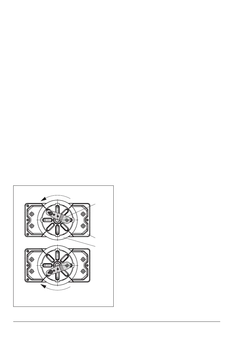
withitsfollowerpin(Fig.22).
1
4
Actuator turning
counterclockwise
Actuator turning
clockwise
Fig.22: Direction of rotation
6
6.1
7
8
1
1.1
1.2
2
4.1
3
10.1
10
11
5
4.3
4
4.2
4.1
3
5.1
5
10.1
10
4.3
4
4.2
1 Lever
1.1 Nut
1.2 Disk spring
2 Follower pin
3 Adapter
4 Coupling wheel
4.1 Screw
4.2 Disk spring
4.3 Adhesive label
5 Actuator shaft or
adapter
5.1 Adapter
6 Connecting plate (only
forG¼)
6.1 Seals
7 Pressure gauge
bracket
8 Pressure gauge
mounting kit
10 Adapter housing
10.1 Screws
11 Spacer
SAMSON Type3278
VETEC S160, VETEC R
Attachment according to VDI/VDE3845
(Sept. 2010) Fixing level 1, AA1 to AA4
size, see section3.8
Use a screw restriction in the signal
pressure output for actuators with
<300cm³volume
Fig.23: Attachment to rotary actuators (heavy-duty version)
 Loading...


