EB 8384-2 EN 67
Mounting and start-up
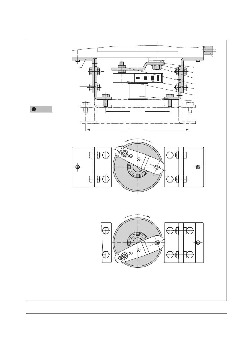
2. Placecouplingwheel(4)withatside
facing the actuator on the follower clamp
(3).RefertoFig.22toalignslotsothatit
matches the direction of rotation when
the valve is in its closed position.
3. Fasten the coupling wheel (4) and follow-
er clamp (3) tightly onto the actuator
shaft using screw (4.1) and disk spring
(4.2).
4. Fasten the bottom pair of brackets (10.1)
with the bends pointing either facing to
the inside or to the outside (depending
on the actuator size) onto the actuator
housing. Position the top pair of brackets
(10) and fasten.
5. Mount connecting plate (6) or pressure
gauge bracket (7) with pressure gauges
on the positioner, making sure the two
seals are seated properly. Double-acting
springless rotary actuators require the
useofareversingamplieronthecon-
Fig.20: Mounting the coupling wheel on
Type3278
Legend for Fig.20 and Fig.21
1 Lever
1.1 Nut
1.2 Disk spring
2 Follower pin
3 Follower clamp
4 Coupling wheel
4.1 Screw
4.2 Disk spring
4.3 Scale plate
5 Actuator shaft
AdapterforType3278
6 Connecting plate
6.1 Seals
7 Pressure gauge bracket
8 Pressure gauge mounting kit
10 Top pair of brackets
10.1 Bottom pair of brackets
10
10.1
6
(7, 8)
1.1
2
4.3
5
4
1.2
1
130 mm
80 mm
NOTICE
!
Only use the connecting
plate (6) included in the ac-
cessories to connect supply
and output.
Never screw threaded parts
directly into housing.
Control valve opens counterclockwise
Control valve opens clockwise
Slot
Slot
Fig.21: Attachment to rotary actuators
 Loading...


