EB 8384-2 EN 65
Mounting and start-up
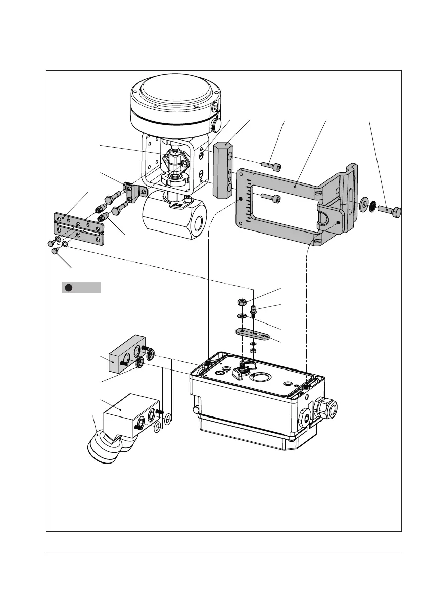
5.7 Attachment to Type3510
Micro-ow Valve
Î RefertoFig.19
Î Requiredmountingpartsandaccesso-
ries:Table4onpage25.
Î Observetraveltablesonpage28.
The positioner is attached to the valve yoke
using a bracket.
1. Fasten the bracket (9.1) to the stem con-
nector.
2. Screw the two bolts (9.2) to the bracket
(9.1) of the stem connector (9), place the
follower plate (3) on top and use the
screws (9.3) for fastening.
3. Mount the travel indication scale (acces-
sories) to the outer side of the yoke using
the hex screws (12.1), ensuring that the
scale is aligned with the stem connector.
4. Fasten the hex bar (11) onto the outer
side of yoke by screwing the M8 screws
(11.1) directly into the holes on the yoke.
5. Fasten the bracket (10) to the hex bar us-
ing the hex screw (10.1), washer and
tooth lock washer.
6. Mount connecting plate (6) or pressure
gauge bracket (7) with pressure gauges
on the positioner, making sure the two
seals are seated properly.
7. Unscrew the standard M lever (1) includ-
ing follower pin (2) from the positioner
shaft.
8. Take the S lever (1) and screw the follow-
er pin (2) in the hole for pin position 17.
10.1
1
2
1.1
1.2
6.1
6
7
8
10
9
9.1
11 11.1
3
12.1
9.2
9.3
S lever
NOTICE
!
Only use the connecting plate (6)
included in the accessories to connect
supply and output.
Never screw threaded parts directly
into housing.
1 Lever
1.1 Nut
1.2 Disk spring
2 Follower pin
3 Follower plate
6 Connecting plate
6.1 Seals
7 Pressure gauge bracket
8 Pressure gauge
mounting kit
9 Stem connector
9.1 Bracket
9.2 Bolt
9.3 Screws
10 Bracket
10.1 Screw
11 Hex bar
11.1 Screws
12.1 Screws
Fig.19: Attachment to Type3510 Micro-ow Valve
 Loading...


