EB 8384-2 EN 99
Operating the positioner
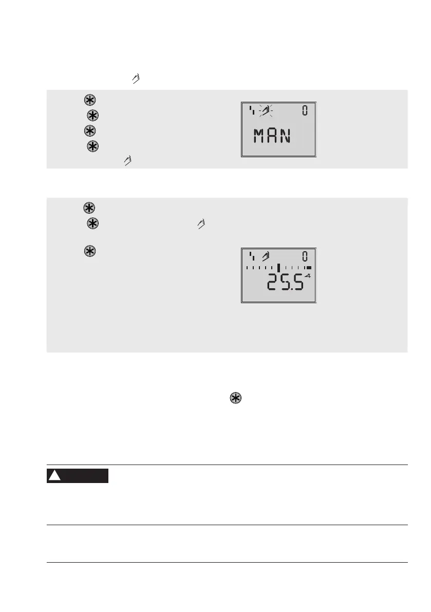
Select manual mode ( ):
1. Turn untilCode0appears.
2. Press
, the code number 0 blinks.
3. Turn
until MAN appears.
4. Press
. The positioner changes to the
manual mode (
).
Operating mode
Default: MAN
Check the operating range:
5. Turn untilCode1appears.
6. Press , the code number 1 and icon
blink.
7. Turn until the pressure in the positioner
builds up and the control valve moves to its
nalpositionssothatthetravel/anglecan
be checked.
The angle of rotation of the lever on the
back of the positioner is indicated.
A horizontal lever (mid position) is equal to
0°.
Manual set point w
(current angle of
rotation is indicated)
To ensure the positioner is working properly, the outer bar elements must not blink while the
valve is moving through the operating range.
ExitCode1bypressingtherotarypushbutton( ).
The permissible range has been exceeded when the displayed angle is more than 30° and
the outer right or left bar element blinks. The positioner goes to the fail-safe position (SAFE).
Aftercancelingthefail-safeposition(SAFE)(seesection7.11.2)itisabsolutely essential that
youchecktheleverandpinpositionasdescribedinsection5.
Risk of injury due to the actuator stem extending or retracting.
Before exchanging the lever or changing the pin position, disconnect the supply air and
electrical auxiliary power.
WARNING
!
 Loading...


