EasyManuals Logo

Samsung mini DVM Series User Manual

Samsung mini DVM Series
522 pages
To Next Page IconTo Next Page
To Previous Page IconTo Previous Page
Page #367 background imageLoading...
Page #367 background image
Samsung Electronics10-11
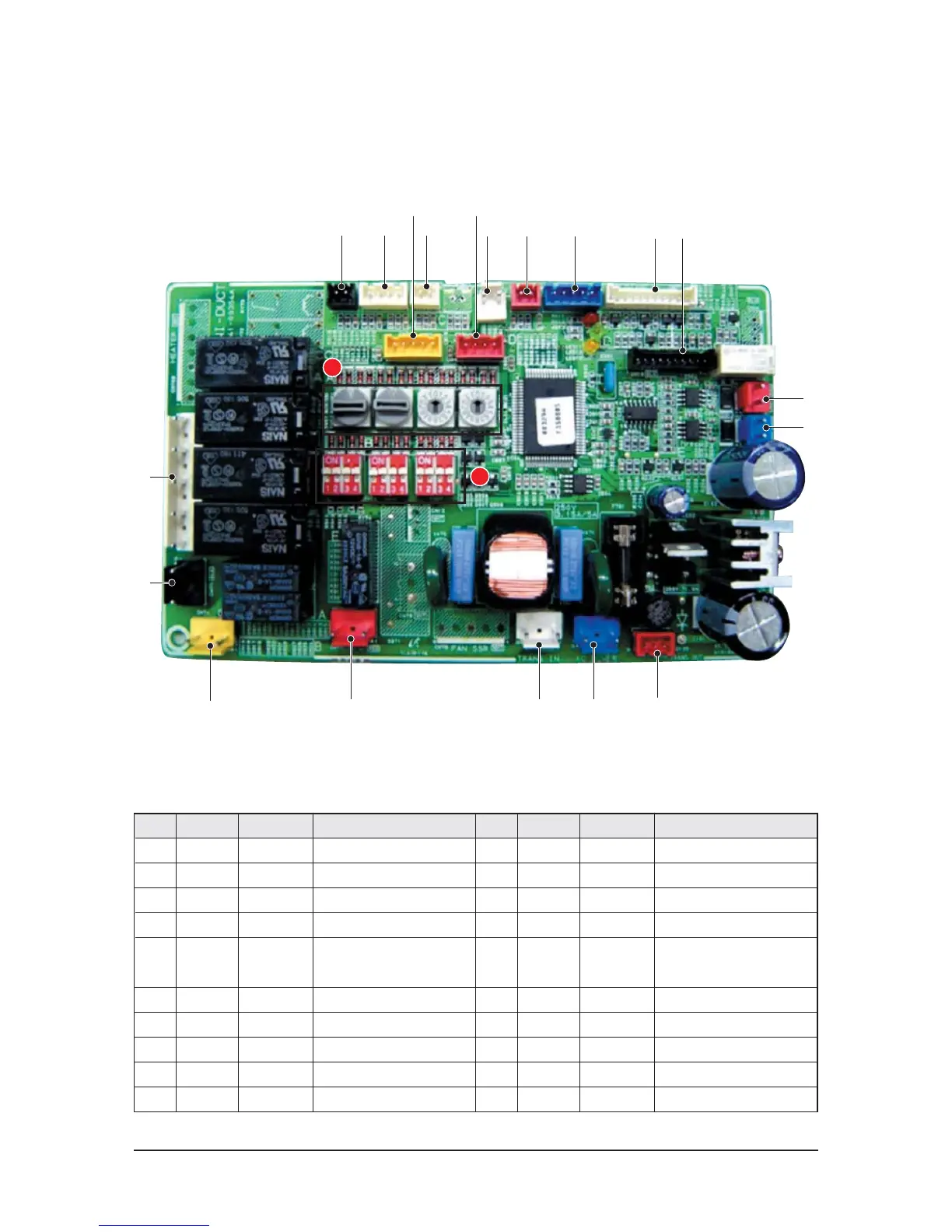
PCB Diagram
10-1-6 Duct type(High & Low Pressure)
! @
5 4
#
$ % ^
&
No. CN# COLOR FUNCTION
!
CN51 BLACK FLOAT S/W
@
CN41 WHITE ROOM/EVA-IN SENSOR
#
CN42 WHITE EVA-OUT SENSOR
$
CN32 WHITE REMOCON DC12V
%
CN83 RED EXTERNAL CONTROL
^
CN62 BLUE EEV
&
CN91 WHITE DISPLAY
*
CN10 BLACK MICOM DOWNLOAD
(
CN31 RED COMM1(OUTDOOR)
)
CN33 BLUE COMM2(REMOCON)
No. CN# COLOR FUNCTION
1
CN11 RED TRANS-OUT
2
CN71 BLUE AC POWER
3
CN72 WHITE TRANS-IN
4
CN81 RED CHECK
5
CN76 YELLOW
EXTERNAL OPTION
PCB CONNECTER
6
CN77 RED HOT COIL
7
CN74 YELLOW DRAIN PUMP
8
CN75 BLACK VENTILATOR
9
CN73 WHITE FAN-MOTOR
A
7
6 3 2
1
)
(
*
8
9
B

Table of Contents

Questions and Answers:

Question and Answer IconNeed help?

Do you have a question about the Samsung mini DVM Series and is the answer not in the manual?

Samsung mini DVM Series Specifications

General IconGeneral
RefrigerantR410A
Cooling Capacity Range (kW)22.4 ~ 33.5
Power Supply380-415V, 3Phase, 50Hz
Control TypeCentralized control, Individual control
Indoor Unit Dimensions (WxHxD)Varies depending on the indoor unit model
Indoor Unit WeightVaries depending on the indoor unit model
Operating Temperature (Heating)-20 ~ 24°C

Related product manuals