EasyManuals Logo

Samsung mini DVM Series User Manual

Samsung mini DVM Series
522 pages
To Next Page IconTo Next Page
To Previous Page IconTo Previous Page
Page #379 background imageLoading...
Page #379 background image
Samsung Electronics10-23
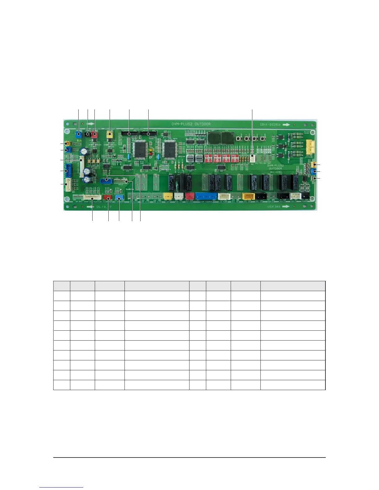
PCB Diagram
10-3-2 MAIN PCB_DC
1 523
*
(
)
! @ # $ % ^ &
4
No. CN# COLOR FUNCTION
!
CN12 BLUE 12V SUPPLY
@
CN13 BLACK 5V SUPPLY
#
CN31 RED INDOOR COMM
$
CN32 YELLOW OUTDOOR COMM
%
CN92 BLACK SUB MICOM DOWN
^
CN91 BLACK MAIN MICOM DOWN
&
OPT1 WHITE CO/HP SELECT
*
CN51 YELLOW COMP1 CT INPUT
(
CN52 BLUE COMP2 CT INPUT
)
CN53 RED COMP3 CT INPUT
No. CN# COLOR FUNCTION
1
CN41 BLUE LOW SENSOR
2
CN12 RED HIGH SENSOR
3
CN44 WHITE COMP/SUCTION SENSOR
4
CN64 BLUE LIQUID EEV
5
CN63 YELLOW EEV2
6
CN47 WHITE OIL/2TUBE/COND SENSOR
7
CN62 BLUE EEV
8
CN49 BLUE OUTAIR SENSOR
9
CN45 YELLOW SUMP SENSOR
0
CN99 WHITE DC SIGNAL TO POWER PCB
9
8
0
7
6

Table of Contents

Questions and Answers:

Question and Answer IconNeed help?

Do you have a question about the Samsung mini DVM Series and is the answer not in the manual?

Samsung mini DVM Series Specifications

General IconGeneral
BrandSamsung
Modelmini DVM Series
CategoryAir Conditioner
LanguageEnglish

Related product manuals