10-18Samsung Electronics
PCB Diagram
No. CN# COLOR FUNCTION
!
CN73 WHITE FAN-MOTOR
@
CN71 BLUE POWER
#
CN82 BLUE IONIZER
$
CN60 WHITE UP-DOWN LOUVER
%
CN44 BLUE RPM-FEEDBACK
^
CN41 WHITE ROOM/EVA-IN SENSOR
&
CN42 WHITE EVA-OUT SENSOR
*
CN31 RED COMM1(OUTDOOR)
No. CN# COLOR FUNCTION
(
CN33 BLUE COMM2(REMOCON)
)
CN32 WHITE REMOCON DC 12V
1
CN61 BLACK MAIN-SUB CONNECTOR
2
CN91 WHITE DISPLAY&MODULE
3
CN10 BLACK DOWNLOAD CONNECTOR
4
CN62 BLUE EEV
SUB PCB
5
CN61 BLACK MAIN-SUB CONNECTOR
No. SW Function ON OFF
K1 Wired remote control not use use
K2 Centralized control not use use
K3 RPM up not use use
K4 Option drain pump N/A N/A
K5 Heating thermo-off +2˚C +5˚C
K6 Filter signal display 1,000hr 2,000hr
K7 Hot water coil N/A N/A
K8 Electrical heater N/A N/A
K9 Min.EEV step at heating fix 80step 0 or 80step
K10 Transmitter grouping N/A N/A
K11 External Control N/A N/A
K12 Preparation
B
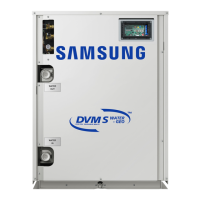
No. SW Function
SW01 SW02
SW03 SW04
Main address
set
(00 ~99)
Centralized control
address set
(00 ~FF)
A

 Loading...