OfficeServ 7400 INSTALLATION
TECHNICAL MANUAL PART 3 MAY 2010
3.35
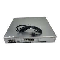
Ports & LEDs Function Description
RUN LED The status of the GWIM/GWIMT
- Off: No power supplied or the operation in abnormal status
- LED turns Green: Normal status
V.35 LED LED turns on when T1/E1 link is connected normally
HSSI LED LED turns on when T3/E3 link is connected normally
P1 ~ P3 LED LED turns on when the relevant links are connected normally
RST Button for resetting the GWIM/GWIMT
CSU/PSU Serial (V.35 on GWIM)
P2 P1
P _______
2
Y _______
15
S _______
14
AA _______
12
R _______
3
V _______
17
T _______
16
X _______
9
C _______
4
H _______
20
D _______
5
U _______
24
E _______
6
W _______
11
B _______
7
_______
18
F _______
8
_______
25
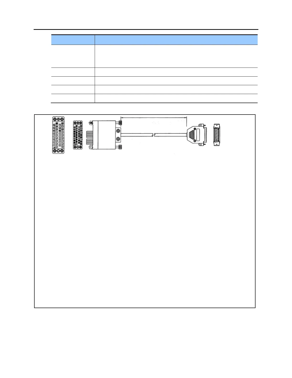
Figure 3.36 V.35 Cable Pin Outs.
This cable connects from the V.35 connector of the GWIM/GWIMT to the customer provided
CSU/DSU. This cable can be ordered separately.