OfficeServ 7400 INSTALLATION
TECHNICAL MANUAL PART 3 JANUARY 2011
3.60
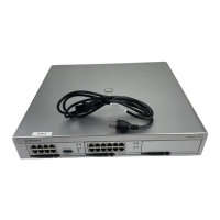
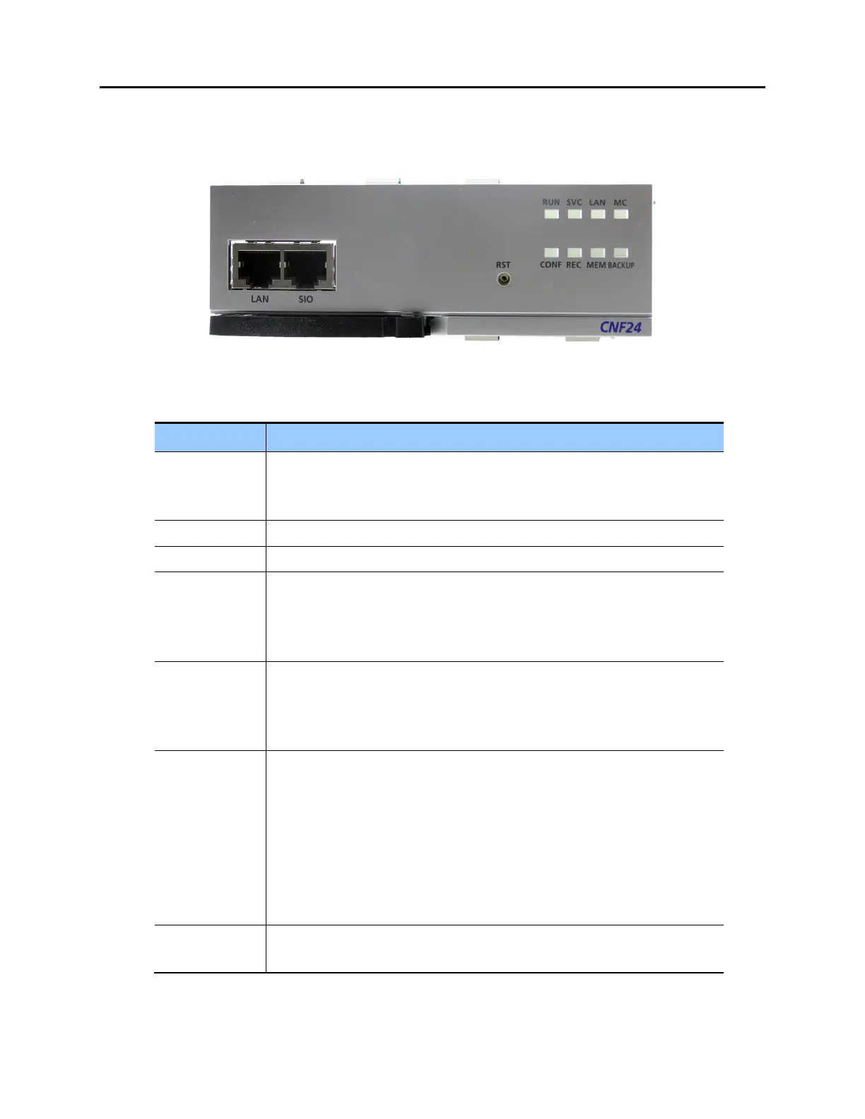
CNF24 FRONT PANEL
The front view of the CNF24 card is shown in the picture below.
Figure 3.53 CNF24 LED Indications
Table 3.25 CNF24 Front Panel Components
Ports & LEDs Function Description
LAN Port that connects the Ethernet.
Connector: RJ45
Cable: CAT 5 cable, UTP.
SIO UART Port (For Testing Only). Serial Port.
RST Button for resetting the CNF24.
RUN LED This LED indicates CNF24 status.
- Off: Power is not being supplied.
- On: Booting.
- Blink: The RAM program is operating.
SVC LED This LED indicates if the CNF24 service is being offered. This LED turns on
when the CNF24 software task can be serviced.
- Blink Red: CNF24 service is not available.
- Blink Green: CNF24 service is available.
LAN LED This LED indicates the status of the Ethernet link.
- Red: Linked as 10 BASE-T Ethernet mode.
- Blink Red: Transmitting/receiving data as 10 BASE-T.
- Green: Linked as 100 BASE-TX Ethernet mode.
- Blink Green: Transmitting/receiving data as 100 BASE-T.
- Orange: Linked as 1000 BASE-TX Ethernet mode.
- Blink Orange: Transmitting/receiving data as 1000 BASE-TX.
-Off: Link off.
MC LED - Blink Green: Auxiliary memory (NAND) is accessed.
- Off: No access.