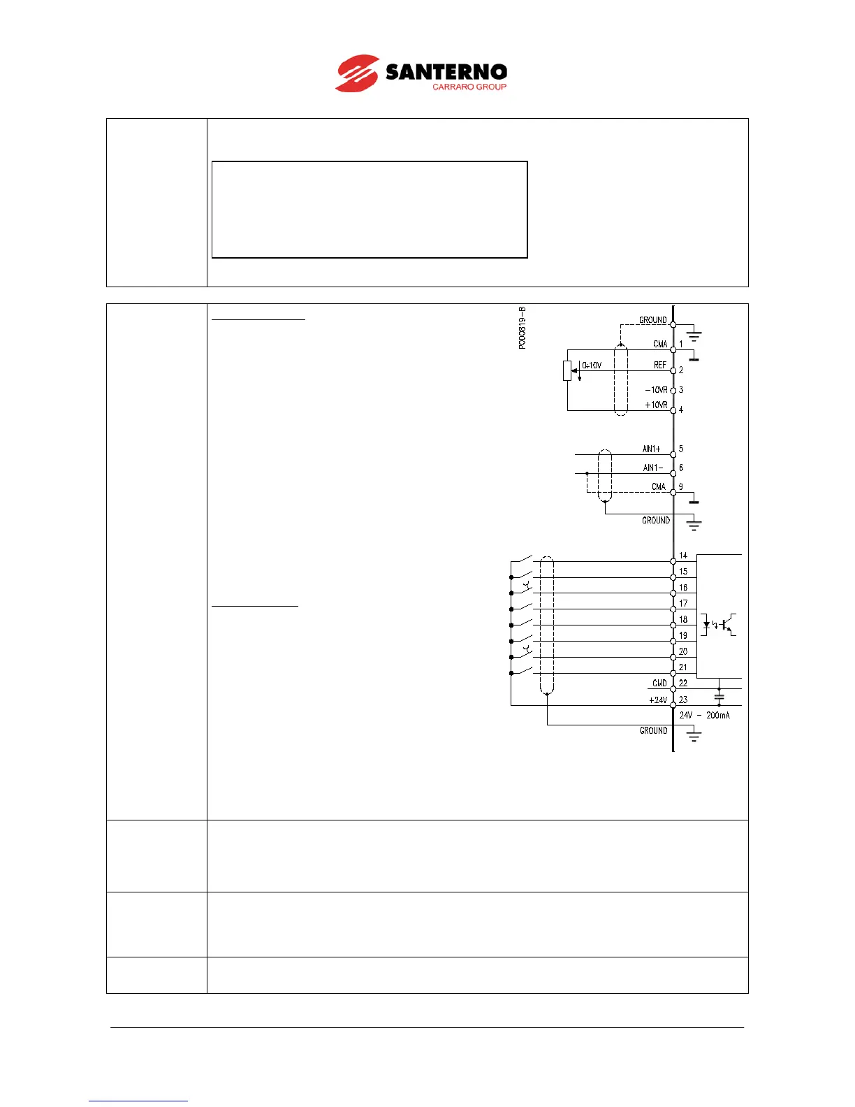
START (MDI1)
ENABLE (MDI2)
RESET (P/B) (MDI3)
MULTISPEED 0 (MDI4)
MULTISPEED 1 (MDI5)
SOURCE SELECTION (MDI6)
LOCAL / REMOTE (P/B) (MDI7)
Cw / CCW (MDI8)
INPUT
ANALOG
4 - 20 mA
:
4 ÷ 20 mA
2 ÷ 10kohm
0 - 10 V
REFERENCE
:
INPUT
After setting the last parameter and moving the cursor forward, the following page will appear:
Press ▲ to quit the Start-up menu. The default page of the system will be displayed.
input (terminal 15).
ii) Activate the
input (terminal 14).
iii) Send speed reference to REF: 0-10V (terminals 1,
2 & 3)
or
Send speed reference to AIN1: 4-20mA (terminals
5 & 6). This requires Source Selection input on
MDI6 to be active (terminal 19).
The RUN LED and REF LED will be lit and the motor
will start. Make sure that the motor is rotating in the
correct direction.
If not, operate on terminal MDI5 (terminal 18)
(CW/CCW) or open the
terminals.
Shut off the drive, wait at least 20 minutes and swap
two of the motor phases.
input (terminal 15).
ii) Press the
button on the keypad.
iii) The L-CMD and L-REF LEDs will be lit.
iv) Press the
button.
v) Hold the Up button to increase the speed
reference.
The RUN LED and REF LED will come on and the
motor will start. Make sure that the motor is rotating in
the correct direction.
If not, press the
. Shut off the drive, wait at least 20 minutes and swap
two of the motor phases.
If no failure occurred, go to the next step. Otherwise, check the drive connections paying particular attention
to supply voltages, DC link and input reference.
Also check if alarm messages are displayed. In the MEASURES MENU
, check values in the Fault List for the
), the supply voltage to the drive (
M029), and the
condition of control terminals (M033). Check to see if these readouts match with the measured values.
7) Additional
parameter
alterations:
user level, adjustments can be made to a limited number of parameters. The SINUS PENTA
has a wide range of functions; to access these function, set the user level to
accordingly (refer to Sinus Penta’s Programming
If an alarm trips, find the cause respon
sible for the alarm and reset the equipment. Enable MDI3
(terminal 16) or press the