Test Run and Others
5
TD831077
V-4
1. Test Run
1-2. Monitor and self-diagnostic function
7 Monitor function for CCU (CR-DYPTG) in PC unit
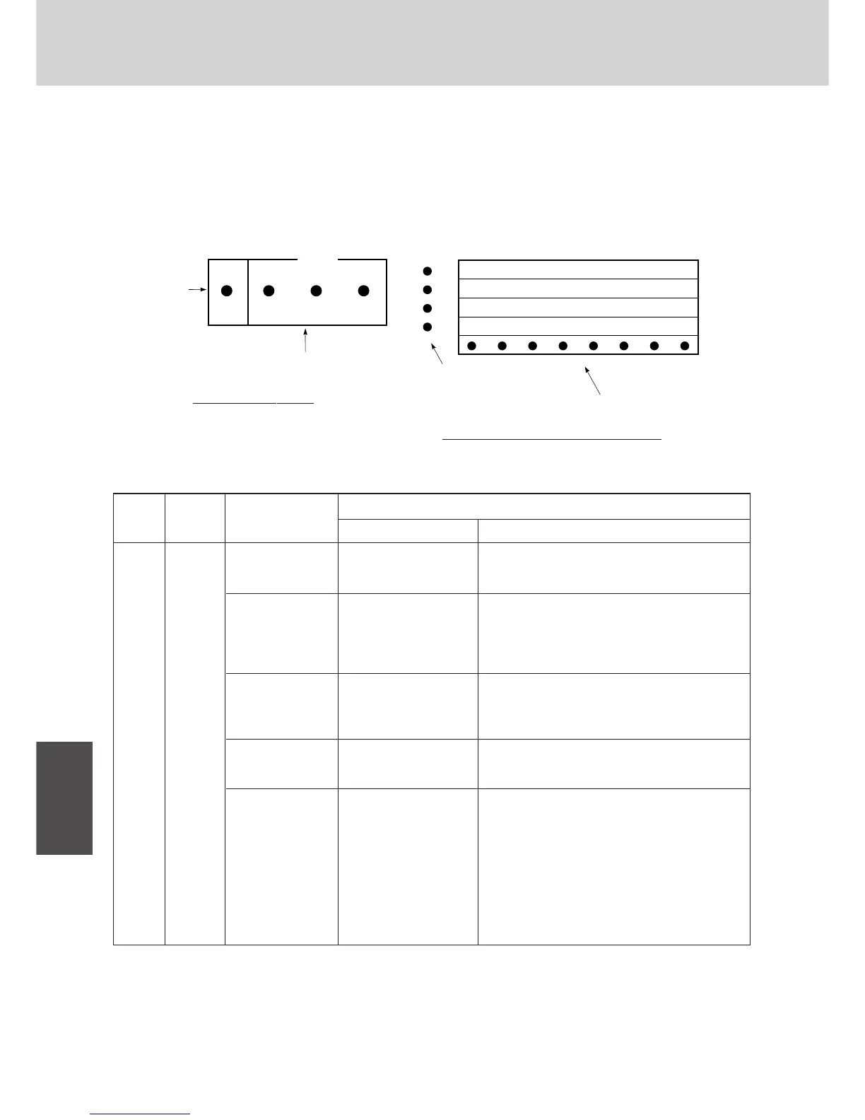
By selecting the Item SW (S7) and Select SW (S8), the LED will display all the necessary information to be monitored.
The monitored information stored in memory can be deleted by turning off the power supply.
¶ Location and name of LED on CCU in PC unit.
LED indicating the number of indoor units
¶ Display messages when using the item and select switches
RUN / ALARM LED MESSAGE LED
Display of the number of indoor units
Display of the number of indoor units
Vertical LED : Lights up unit where alarm is
being issued [unit No. 1 (PC unit),
unit No. 2 and No. 3 (AD units)]
Horizontal LED : Displays alarm messages
Vertical LED : Displays progress of auto.
address operation
Horizontal LED : Displays alarm messages
Vertical LED : All off
Horizontal LED : 1 and 2 blink alternately
Note) CB: CCU
Message displayed
O ●●●
(●● ● ●)
RUN
INDOOR OUTDOOR
CB
OO ●●
RUN
INDOOR OUTDOOR
CB
O ● O ●
(●● O ●)
RUN
INDOOR OUTDOOR
CB
O ●●O
(●● ● O)
RUN
INDOOR OUTDOOR
CB
O ●●●
(●● ● ●)
RUN
INDOOR OUTDOOR
CB
∗ If either outdoor or CB
alarm message is
displayed during auto.
address operation, the
alarm can be con-
formed by selecting “4”
on the Item switch.
Operation / Alarm LED
Item
Display of the number
of connected indoor
units
Display of alarm
messages for indoor
unit
∗Displayed at the
time of operation
Display of alarm
messages for
outdoor unit
Display of alarm
messages for CCU
Display during auto.
address operation
ITEM
SW (S7)
0~F
0
(Initial
setting)
SELECT
SW (S8)
1~4
–
RUN
Alarm display (yellow × 3)
CB: CCU
Operational
display (green)
INDOOR OUTDOOR
ALARM
CB
1708_M_I
Display of outdoor
unit number (red × 4)
Display of the number of indoor units (red × 8)
4
3
2
1
32
24
16
8
31
23
15
7
30
22
14
6
29
MESSAGE
21
13
5
28
20
12
4
27
19
11
3
26
18
10
2
25
17
9
1
1709_M_I
Fig. 1-7
Fig. 1-8
O : light ON / blink ● : light OFF
 Loading...
