Operating Instructions Cubis
®
MCA 3
Contents
Contents
1 About these Instructions...........................7
1.1 Scope..........................................7
1.2 Symbols Used..................................7
1.2.1 Warnings in Operating Instructions ....7
1.2.2 Other Symbols .........................8
1.3 Target Groups .................................8
2 Safety Instructions .................................9
2.1 Intended Use ..................................9
2.1.1 Modifications to the Device ............9
2.1.2 Repairs to the Device...................9
2.2 Personnel Qualification...................... 10
2.3 Significance of these Instructions............ 10
2.4 Functionality of the Device .................. 10
2.5 Safety Information on the Device............ 10
2.6 Electrical Equipment .........................11
2.6.1 Damage to the
Device’s Electrical Equipment ........11
2.6.2 Working on the
Device’s Electrical Equipment ........11
2.6.3 Power Supply Unit
and Power Supply Cable ..............11
2.7 Conduct in an Emergency....................11
2.8 Accessories, Consumables,
and Spare Parts ...............................12
2.9 Glass Breakage ...............................12
3 Device Description................................13
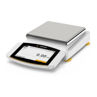
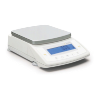
3.1 Device Overview..............................13
3.2 Draft Shield . . . . . . . . . . . . . . . . . . . . . . . . . . . . . . . . . . .14
3.3 Weighing Pan
and Associated Components . . . . . . . . . . . . . . . . .15
3.4 Connections and Components
on the Weighing Module .....................16
3.4.1 Analytical Balance
and Precision Balance.................16
3.4.2 Semi-microbalance
with Electronics Module ..............17
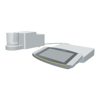
3.5 Connections and Components
on the Electronics Module....................17
3.6 Connections on the
Display and Control Unit......................18
3.7 Safety Equipment.............................18
3.7.1 Protective Caps on the Analytical
Balance and Precision Balance........18
3.7.2 Protective Caps
on the Electronics Module ............19
3.8 Conformity-assessed Devices ...............20
3.9 Symbols on the Device ......................20
4 Operating Design .................................21
4.1 Operating Elements in the Main Menu .......21
4.2 Operating Elements in Task Management...22
4.3 Operating Elements
in the Weighing Display......................23
4.4 Advanced Operator Guidance...............24
4.5 Messages ....................................25
4.6 Status Center ................................26
4.7 Keypad ......................................27
4.8 Status Display of the Buttons ................27
4.9 Buttons in the Operating Display . . . . . . . . . . . . 28
4.9.1 Buttons for Navigation
or Organization in Displays ...........28
4.9.2 Buttons for Editing
or Managing Entries..................29
4.9.3 Buttons for Weighing,
Printing, and Export Functions .......30
4.10 Displays in the Operating Display............32
4.11 User Management...........................33
4.11.1 User Profiles..........................33
4.11.2 User Login............................33
4.12 Weighing and Print Profiles..................33
4.13 Tasks and Applications.......................33
4.14 Menu Structure..............................34
4.14.1 Main Menu . . . . . . . . . . . . . . . . . . . . . . . . . . . 34
4.14.2 “Settings” Menu ......................35
4.15 Navigating the Menus ........................41
5 Installation ........................................43
5.1 Scope of Delivery ............................43
5.2 Selecting an Installation Site.................44
5.3 Unpacking the Device .......................44
5.4 Removing the Display and Control Unit .....45
5.4.1 Positioning the
Display and Control Unit .............45
5.5 Connecting the Ethernet Cable .............46
5.6 Preparing Below-balance Weighing . . . . . . . . . 46
5.7 Installing a Device with an Analytical
Draft Shield or Flat Glass Draft Shield .......48
5.7.1 Positioning the Weighing Pan
andAssociatedComponents.........48
5.7.2 Installing the Analytical Draft Shield..49
5.7.3 Installing the Flat Glass Draft Shield..50
5.8 Installing a Device
with a Frame Draft Shield....................50
5.8.1 Positioning the Weighing Pan
andAssociatedComponents.........50
5.9 Connecting the Electronics Module
(Onlyfor Semi-microbalance) ................51
 Loading...