Testing Digital I/O
Step Key (or instruction) Display/Printout
1. Test connector for RS-232 data output Connect universal key (pin 15) with
(see “Pin Assignment Chart”) the digital I/O (pin 16 … pin 19) tested
2. Select
Hardware Test see the previous page
3. Select
Test interface and confirm u
4. Select
Test digital I/O function y
and confirm u
“Test error” or “Test OK” is displayed
for each I/O port. Testing of the first port
begins again after the last port
5. Exit digital I/O test 2 + c
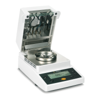
Testing the Heater
Step Key (or instruction) Display/Printout
1. Select
Hardware Test see the previous page
2. Select
Test heater and confirm y
u
3. Start heater test:
START function u
On starting, the current temperature
(here e.g. 123 °C) and the test time
(here e.g. 1.5 minutes) are displayed
If the sample chamber is opened,
the test is paused until the sample chamber
is closed again
The device reaches the target temperature
after a brief period
4. Exit heater test c
36
isoTEST HARDWARE INTERFACE
Test SBI communication
Test Digital-I/O
HARDWARE INTERFACE DIG.-I/O
Result:
HARDWARE INTERFACE DIG.-I/O
1: Test error
Result: 2: Test OK
3: Test error
4: Test error
25
END
HEATER TST 160
o
C Verzög. 2sec
S
o
C
STARTSETUP
123
ENDE
HEATER TST 160
o
C 160
o
C 1.5min
S
o
C
STARTSETUP
160
ENDE
HEATER TST 160
o
C 160
o
C 11.2min
S
o
C
STARTSETUP