9
47 233 4 Reserved
Fields indicated by an N/A mark are padded with ASCII zeros.
c
The parameter limits are as follows:
Vmax
(690 V input option) = 828V @ PT Ratio = 1
Vmax
(690 V input option) = 144 × PT Ratio [V] @ PT Ratio > 1
Vmax
(120 V input option) =144 × PT Ratio [V]
Imax
(50% over-range) = 1.5 × CT primary current [A]
Pmax
= (Imax × Vmax × 3)/1000 [kW] if wiring mode is 4LN3 or 3LN3
Pmax
= (Imax
×
Vmax
×
2)/1000 [kW] if wiring mode is 4LL3, 3OP2, 3DIR2, 3OP3 or 3LL3
d
When the value width is greater than the field resolution, the reading is converted to higher units and
transmitted with a decimal point. The right-most digits of the reading are truncated.
e
Energy readings are transmitted in MWh, Mvarh and MVAh units with a decimal point. If the energy
value exceeds the field resolution, the right-most digits are truncated. The energy roll value is user
selectable (see Section 5.4).
f
For negative power factor, the minus sign is transmitted before a decimal point as shown in the table.
g
To get block interval demand readings, set the number of demand periods equal to 1 (see Table 4-4).
h
When the 4LN3 or 3LN3 wiring mode is selected, the voltages will be line-to-neutral; for any other
wiring mode, they will be line-to-line voltages.
(P) available in the PM130P and PM130E
(E) available in the PM130E
4.2 Basic Setup
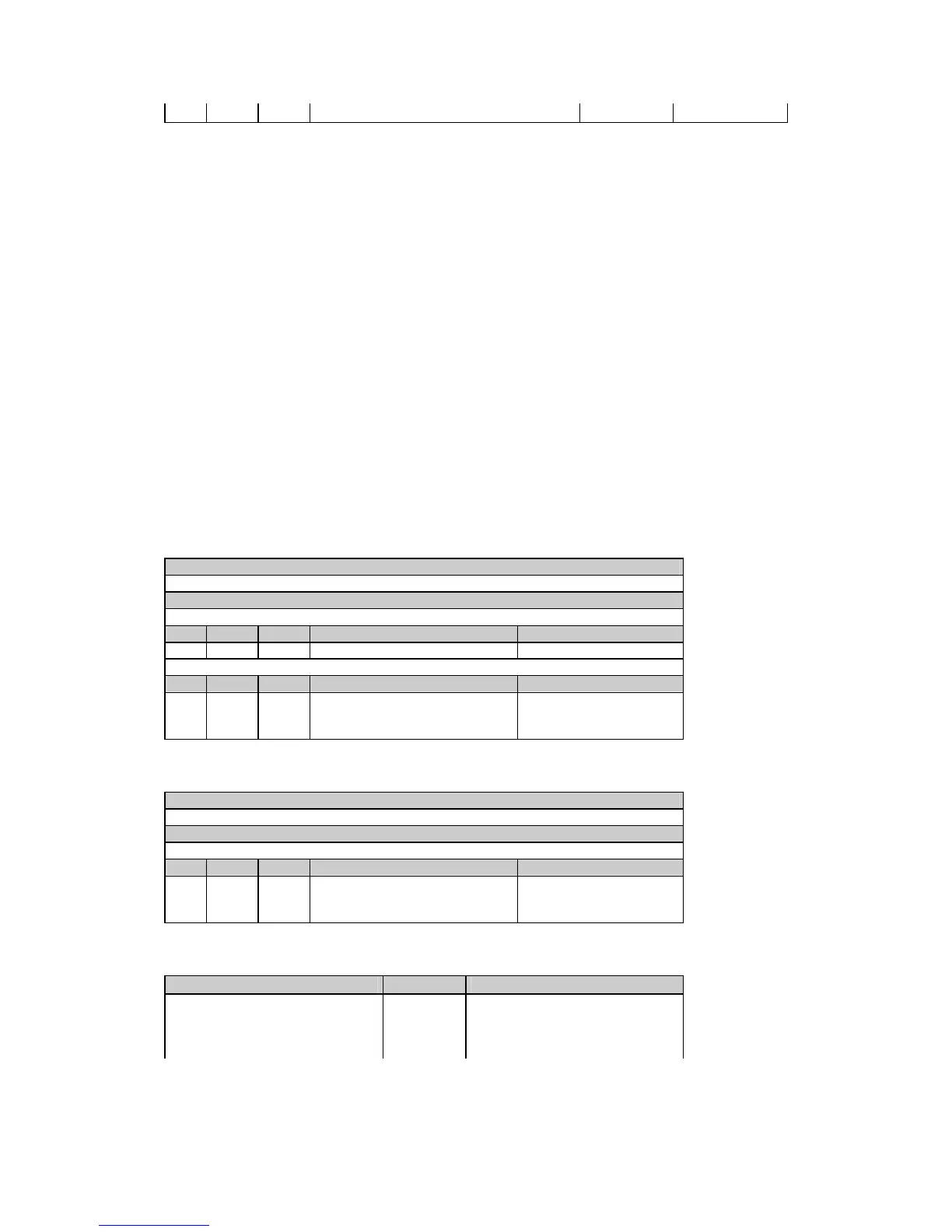
Table 4-2 Read Request
Message type (ASCII)
1
Message body (decimal)
Request
Field Offset Length Parameter Range
1 0 3 Parameter identifier see Table 4-4
Response
Field Offset Length Parameter Range
1 0 3 Parameter identifier see Table 4-4
2 3 4 Not used permanently set to 00.0
3 7 6 Parameter value see Table 4-4
Table 4-3 Write Request
Message type (ASCII)
2
Message body (decimal)
Request/Response
Field Offset Length Parameter Range
1 0 3 Parameter identifier see Table 4-4
2 3 4 Not used set to 00.0
3 7 6 Parameter value see Table 4-4
Table 4-4 Basic Setup Parameters
Parameter Identifier Range
Wiring mode
c
W40 0 = 3OP2, 1 = 4LN3, 2 = 3DIR2,
3 = 4LL3, 4 = 3OP3, 5 = 3LN3,
6 = 3LL3
PT ratio U14 1.0 to 6500.0

 Loading...


