5
2 ASCII FRAMING
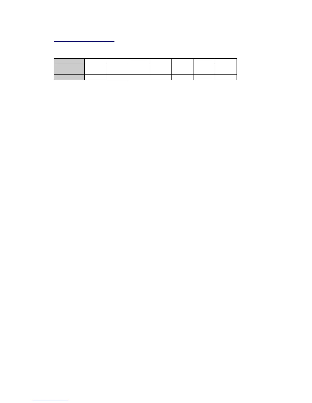
The following specifies the ASCII message frame:
Field No.
1 2 3 4 5 6 7
Contents
SYNC
(!)
Message
length
Slave
address
Message
type
Message
body
Check
sum
Trailer
(CRLF)
Length, char
1 3 2 1 0 to 246 1 2
SYNC
Synchronization character: one character '!' (ASCII 33), used for starting synchronization.
Message length
The length of the message including only number of bytes in fields #2, #3, #4 and #5. Contains
three characters between '006' and '252'.
Slave address
Two characters between '00' and '99'. The instrument with address '00' responds to requests
with any incoming address. For RS-422/RS-485 communications (multi-drop mode), this field
must NEVER be zero.
Message type
One character representing the type of a host request. A list of the message types is shown in
Tables 2-1 and 2-2. Note that they are case-sensitive.
Message body
Contains the message parameters in ASCII representation. All parameter fields have a fixed
format. The data fields vary in length depending on the data type. Unless otherwise indicated,
the parameters should be right justified and left-padded with zeros. Most parameters are
represented in ASCII hexadecimal notation, and in some cases (to provide compatibility with old
instruments) a decimal representation is preserved.
In a decimal notation, the parameters are transferred in a decimal representation as is, i.e., no
conversion is needed. When a value is between 0 and 1, a decimal point is placed in the data
field. When the whole value exceeds the field range, it is divided by 1000 and truncated to the
right. A decimal point is placed after the thousands to denote that the value has been truncated
and must be multiplied by 1000 before it will be processed.
In a hexadecimal notation, all parameters are whole binary numbers of a 1-byte, 2-byte or 4-
byte length. Each byte is transferred as two hexadecimal digits in ASCII notation (i.e., ASCII
printable characters 0-9, A-F are used to represent hexadecimal digits 0h-9h, 0ah-0fh). Each
byte is transmitted high order digit first. Each 2-byte and 4-byte parameter is transmitted high
order bytes first. Negative numbers are transmitted in 2-complement code.
To represent numbers between 0 and 1, a modulus method is used. Fractional numbers are
divided by a modulus and stored in the Powermeter as whole numbers. The modulus depends
on the number of decimal digits in the fractional part, i.e., on the value precision. The modulus is
given in the form ×0.1, ×0.01 or ×0.001. For example, the frequency value of 50.01 Hz having
the modulus of
×
0.01 will be received from the instrument as the whole number of 5001. To
process the value received from the instrument in this format, the value must be multiplied by
the modulus. To write such a number to the instrument, the number must be divided by the
modulus.

 Loading...


