10
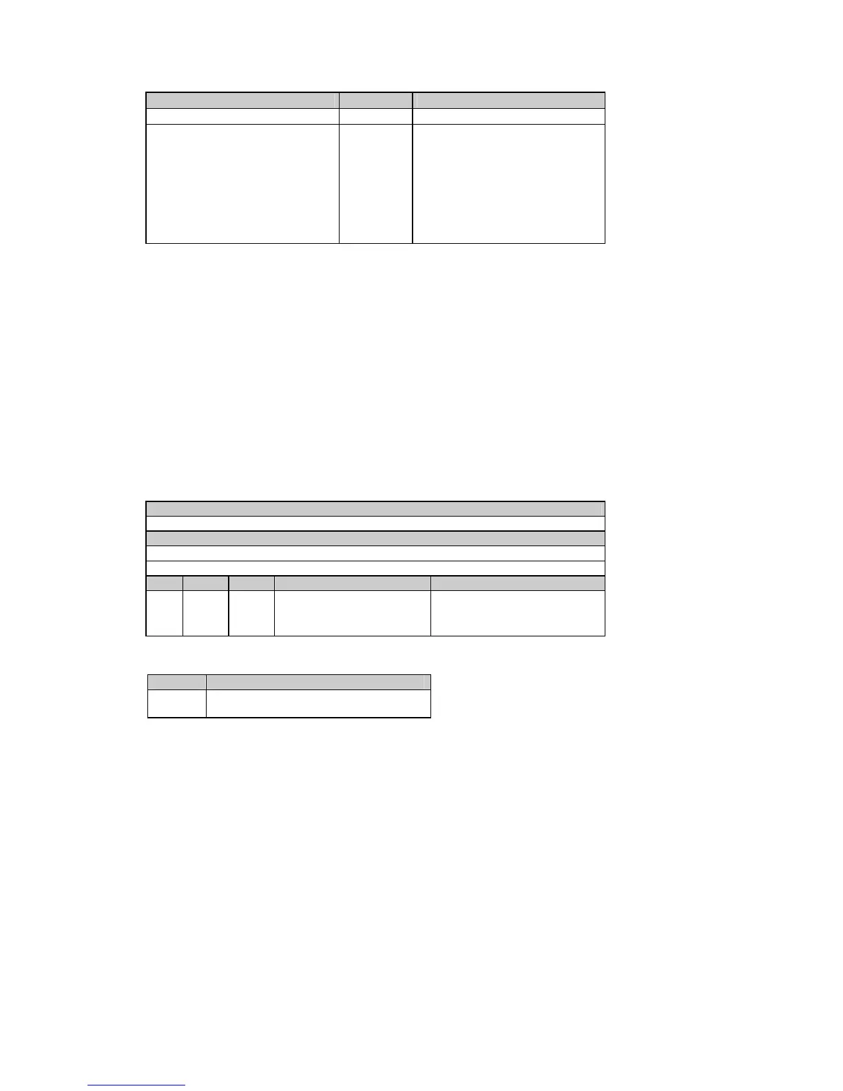
Parameter Identifier Range
CT primary current I17 1 to 50000 A
Power demand period (E) D11 1,2,5,10,15,20,30,60 min
255 = external synchronization
d
The number of demand periods (E) F47 1 - 15
Volt/ampere demand period C12 0 to 1800 sec
Averaging buffer size S41 8, 16, 32
Reset enable/disable R42 0 = disable, 1 = enable
Nominal frequency Q51 50, 60
Reserved Q52
c
The wiring mode options are as follows:
3OP2 - 3-wire open delta using 2 CTs (2 element)
4LN3 - 4-wire WYE using 3 PTs (3 element), line to neutral voltage readings
3DIR2 - 3-wire direct connection using 2 CTs (2 element)
4LL3 - 4-wire WYE using 3 PTs (3 element), line to line voltage readings
3OP3 - 3-wire open delta using 3 CTs (2 1/2 element)
3LN3 - 4-wire WYE using 2 PTs (2 1/2 element), line to neutral voltage readings
3LL3 - 4-wire WYE using 2 PTs (2 1/2 element), line to line voltage readings
d
Synchronization of power demand interval can be made through communications using the
Synchronize power demand interval command (see Table 5-23)
(E) available in the PM130E
4.3 Instrument Status
Table 4-5 Read Request
Message type (ASCII)
3
Message body (hexadecimal)
Request - no body
Response
Field Offset Length Parameter Range
1 0 8 Not used 00000000
2 8 1 Not used 0
3 9 1 Relay status see Table 4-6
Table 4-6 Relay Status
Bit Description
0-2 N/A (permanently set to 1)
3 Relay status
Bit meaning: 0 = relay operated, 1 = relay released

 Loading...


